
 | ||
The Shifting Bottleneck Heuristic is a procedure intended to minimize the time it takes to do work, or specifically, the makespan in a job shop. The makespan is defined as the amount of time, from start to finish, to complete a set of multi-machine jobs where machine order is pre-set for each job. Assuming that the jobs are actually competing for the same resources (machines) then there will always be one or more resources that act as a 'bottleneck' in the processing. This heuristic, or 'rule of thumb' procedure minimises the effect of the bottleneck. The Shifting Bottleneck Heuristic is intended for job shops with a finite number of jobs and a finite number of machines.
Contents
Uses
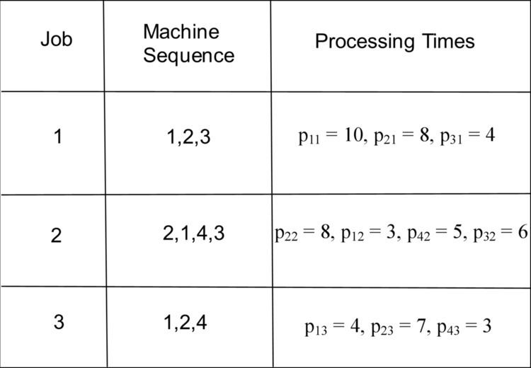
The Shifting Bottleneck Heuristic is used in manufacturing and service industries that include job shops with constraints on the order that the machines must be used for each job. A good example of a service industry that may use this technique is a hospital. The different areas within a hospital, such as physical examination, x-ray booth, cat scan, or surgery, could all be considered machines for this particular application. A precedence constraint in this context is when one machine must be used before another machine on any given job (or patient). These types of problems with multiple machines are known to be computationally very difficult. The processing time of each job on each machine is given (see chart on right for an example). Job j being performed on machine i is denoted ij. It is assumed that each machine can only work on one job at a time. The objective is to determine the schedule that will produce the shortest makespan.
Procedure
First graph
The first step is to draw out the precedence constraints in a graphical form called a graph (See Original Drawing picture). Each job originates at the "source", which we will label U on the graph. Each job will finish in a "sink" of jobs, which we will label V on the graph. Each row of nodes in the graph represents a job. Each node on the graph represents a task that is part of the job, the second number confirms the job being performed and the first number indicates what machine is being used for this task. At this point, the initial throughput time of each job should be calculated by adding up the processing times that the job takes on each of the machines (or rows). After the throughput time for each job has been calculated, the makespan for the system is determined by the longest throughput time of any individual job. This assumes no resource conflicts and gives a makespan of 22.
First iteration
The next step is to determine which resource/machine is currently the bottleneck. This is done by considering the production time, denoted pij, that each job takes on each machine, the release time of each job on each respective machine, and the due date of each job for each respective machine. The release time, denoted rij, is determined by adding up the processing times of all of the jobs that have to be performed on the machine before the respective job can be performed. The due date, denoted dij, is determined by subtracting the processing times of the jobs succeeding the job on the respective machine from the makespan. Once all of this is determined, the minimum lateness for each machine needs to be determined. This is accomplished by finding the path for each machine that reduces the maximum lateness seen for all jobs on the respective machine. One way to find the optimal path is to use a branch and bound technique. See the chart to the right for an example of this data. Once the maximum lateness is determined for each of the respective machines, the machine with the largest maximum lateness is the bottleneck. If there is no maximum lateness on any of the machines, one can draw all of the machines’ optimal sequences in the job diagram. If there are two machines with the same maximum lateness, either one can be chosen for the bottleneck. All of this work is considered the first iteration.
Once the bottleneck has been determined, the path for the machine needs to be included in the drawing of jobs (See Iteration 1 Drawing, where the colored arrows represent disjunctive constraints). These new paths can be considered the disjunctive constraints and they need to be taken into consideration when determining the new makespan. The disjunctive constraints are the machine constraints in our job shop. The new makespan will be the old makespan plus the maximum lateness of the machine determined to be the bottleneck.
Second iteration
The next step is to perform a new analysis for each of the remaining machines. The differences now are there is a new makespan, and the precedence constraints need to be considered as well as the disjunctive constraints when determining the release date of each job on the machine. The longest path to get to the respective job, coming from comparing the processing times of the preceding jobs for disjunctive constraints and precedence constraints, will be the new release date. The due dates will be the time that the given job can be finished on the respective machine and still have enough time to finish the job on the proceeding machines within the makespan. The proceeding jobs are known from the precedence constraints. Draw out the new disjunctive constraints on your drawing (see Iteration 2). This is considered the second iteration.
Again, determine which machine is the new bottleneck. The new makespan is the old makespan plus the maximum lateness from the new bottleneck. Again, if the maximum lateness on all machines is zero then use all the paths for the disjunctive constraints on the drawing and the makespan is still the same as it was before.
Further iterations
This process is repeated until all machines have been accounted for or the maximum lateness is zero on all respective remaining machines. Each time the process is repeated, it is considered an iteration and all of the disjunctive constraints may be drawn on the job and machine diagram. For our example, the next iteration provided us with zero for the maximum lateness on machines 3 and 4, so their optimal sequences can be included in the drawing (see Iteration 3).
At this point the Shifting Bottleneck Heuristic is complete. The drawing should now include all precedence constraints and all disjunctive constraints. The final makespan is the original makespan plus all of the maximum latenesses from each of the respective bottlenecks. It is the lowest amount of time needed complete all of the jobs given these machine and precedence constraints.