
Year created 2003 Speed 100 Mbit/s Redundancy? Yes | No. of devices 511 Hotplugging? Yes Ethernet compatibility? Yes | |
 | ||
Sercos III is the third generation of the Sercos interface, a globally standardized open digital interface for the communication between industrial controls, motion devices, input/output devices (I/O), and Standard Ethernet nodes. Sercos III merges the hard real-time aspects of the Sercos interface with Ethernet. It is based upon and conforms to the Ethernet standard (IEEE 802.3 & ISO/IEC 8802-3). Work began on Sercos III in 2003, with vendors releasing first products supporting it in 2005. In addition to the standard Sercos features cited under the Sercos interface general description, Sercos III also provides:
Contents
- General architecture
- Sercos III cycle
- Telegram format
- Telegram types
- Synchronization
- Physical and data link layers
- Wiring
- Sercos III stack
- Data consistency
- Addressing
- Network topologies
- Line topology
- Ring topology
- Other network topologies
- Infrastructure hardware
- Fieldbus integration
- Application layer profiles
- Redundancy
- Peer communications
- Hot plugging
- Oversampling and time stamping
- Unified Communication UC Channel
- UCC access
- Common network infrastructure
- Functional safety support
- Sercos IO Profile
- Sercos Energy Profile
- Driver software
- Certification
- References
General architecture
In order to achieve the throughput and jitter requirements required in the applications the interface is designed for, Sercos III operates primarily in a Master/Slave arrangement exchanging cyclic data between nodes. The master initiates all data transmission during a Sercos real-time cycle. All data transmissions begin and end at the master (circular).
Sercos III cycle
Communication across a Sercos III network occurs in strict cyclic intervals. A cycle time is chosen by the user for a given application, ranging from 31.25 µs to 65 ms. Within each cycle, data is exchanged between Sercos III nodes using two types of telegrams: MDTs and ATs (see Telegram Types). After all MDTs and ATs are transmitted, Sercos III nodes allow the remaining time in the cycle to be used as an UC (Unified Communication) Channel, which can be used to exchange data using other formats, such as IP.
The network remains available to UCC traffic until the next cycle begins, at which time the Sercos III nodes close the nodes to UCC traffic again. This is an important distinction. Sercos is purposely designed to provide open access at all ports for other protocols between cyclic real time messages. No tunneling is required. This provides the advantage that any Sercos III node is available, whether Sercos III is in cyclic mode or not, to use other protocols, such as TCP/IP, without any additional hardware to process tunneling. Sercos nodes are specified to provide a store and forward method of buffering non-Sercos messages should they be received at a node while cyclic communication is active.
Telegram format
All Sercos III telegrams conform to the IEEE 802.3 & ISO/IEC 8802-3 MAC (Media Access Control) frame format.
Telegram types
Two main types of telegrams are used within the Sercos III Cycle. The Master Data Telegram (MDT), and the Acknowledge Telegram (AT). Both telegram types are issued by the master (control). The MDT contains information provided by the master to slaves. It is filled by the master, and read by slaves. The AT is issued by the master, but actually populated by each slave with their appropriate response data (feedback values, input states, etc.). More than one slave uses the same AT, filling in its pre-determined area in the AT telegram, updating checksums, and then passing the telegram to the next device. This method reduces the impact of the Ethernet frame overhead on the performance of the network without compromising IEEE 802.3 & ISO/IEC 8802-3. The amount of data sent from the master to slaves, as well as the sum of the data returned by the slaves, may exceed the 802.3-specified maximum 1500-byte data field size. To comply with this limit, Sercos III may use more than one MDT telegram in a cycle, as well as more than one AT telegram (up to 4 in each case).
Synchronization
To achieve true hard real time characteristics, Sercos III, like Sercos I & II, uses a form of synchronization that depends upon a synchronization “mark” issued by the master control at exact equidistant time intervals. All nodes in a Sercos network use this telegram to synchronize all activities in the node. To account for variations in network components, delays are measured in the node-to-node transmissions during phase-up (initialization) of a Sercos network, and those values compensated for during normal operation. Unlike Sercos I & II, where a separate Master Sync Telegram, or MST is used for this purpose, Sercos III includes the MST in the first MDT transmitted. No separate telegram is issued. The time between two MSTs is exactly equal to the designated Sercos cycle time, tScyc.
The synchronization process ensures that cyclical and simultaneous synchronization of all connected devices occurs independently of topology and of the number of devices in Sercos networks.
Physical and data link layers
Sercos III supports standard IEEE 802.3 & ISO/IEC 8802-3 100Base-TX or 100Base-FX (100 Mbit/s baseband) full duplex physical layer (PHY) entities. 802.3-compliant Media-Access Controller (MAC) sub-layers are used. Autonegotiation must be enabled on each PHY, but only 100 Mbit full duplex is supported. Auto (MAU [Media Attachment Unit]-Embedded) Crossover is specified between the two Physical Medium Attachment (PMA) units present with a duplex port. These two units are referred to as the Primary Channel and Secondary Channel in the Sercos III specification. Dual interfaces are required (two duplex interfaces per device). Within the Sercos III specification the dual interfaces are referred to as P1 and P2 (Ports 1 and 2).
Wiring
Installing a Sercos network is easy and does not require infrastructure components such as switches or hubs. All devices are interconnected by patch or crossover cables up to 100 m in length. The Ethernet ports on the devices are interchangeable and can be used to connect standard Ethernet devices such as notebook computers to the network. Every Ethernet and IP protocol on Sercos devices can be accessed without interfering with the real-time protocol and without requiring the real-time operation to be activated.
Sercos III stack
All of the functionality required to configure a Sercos III interface is contained in a stack that is available in both “hard” and “soft” versions. The hard version is widely used for embedded applications (such as drives, I/O modules and micro-controller based motion control), where:
The hardware stack is available in a number of different forms. These currently include:
The maximum jitter allowed with hard-stack-based masters and slaves is less than 1 µs. Using the above stacks yields a jitter similar to Sercos II (35-70 nanoseconds).
Sercos III also supports a “Soft Master”, using a completely software-based stack for the master interface. Since the maximum jitter in such a configuration is dependent upon the operating system of the Master, the maximum jitter may be set by a variable for the Sercos III network when a Soft Master is employed.
For basic Slaves, such as I/O devices, EasySlave-IO, a license-free bitstream variant of the EasySlave is available.
A product that uses an Arduino board as a rapid prototype platform for an application, plus a corresponding shield (add-on module) with a Sercos EasySlave FPGA, plus other peripheral components, is available.
Data consistency
A term usually associated with the IT enterprise, data consistency can also apply to real-time control (see for example Peer to Peer Communication). For this reason, Sercos III specifies that no data be overwritten (destroyed) during a transmission. Every slave on a network may access input and output data for every other slave on the network.
Addressing
Devices must support Ethernet’s MAC addressing, plus the Sercos III addressing. Other addressing schemes are optional.
Network topologies
The Sercos III specification defines two possible network topologies; Ring and Line. To those familiar with other networks, both of them may appear to be configured as a ring. All telegrams begin and end at the master. The Full Duplex feature of the physical layer is used to achieve this.
Line topology
A line topology is the simpler of the two possible arrangements, and provides no redundancy. However, this configuration saves the cost of one cable. In it, only one of the two interfaces on the master is used. Telegrams are issued out of the transmit PMA on the Master’s active port. Either port on the master may be the active one. Sercos III determines this during phase-up (initialization).The first slave receives the telegrams on the connected interface’s receive PMA, modifies them as required, and issues them out on the transmit PMA of the second interface. Each cascading Slave does likewise until the last Slave in the Line is reached. That slave, detecting no Sercos III connection on its second port, folds the telegram back on the receiving interface’s transmit port. The telegram then makes it way through each Slave back to the Master. Note the last slave also emits all Sercos III telegrams on its second port, even though no Sercos III connection is detected. This is for snooping, ring closures (see below), and hot-plugging.
Keep in mind that since the Ethernet destination field in all Sercos III telegrams is the broadcast address of 0xFFFF FFFF FFFF (all 1s), all telegrams issued from this open port will be seen by other devices as broadcast telegrams. This behavior is by design, and cannot be disabled. To avoid taxing networks attached to an open Sercos port, an IP-Switch can be used, or alternately a managed Ethernet switch programmed to block broadcast telegrams received from the Sercos port can be used. Starting with Sercos III specification version 1.3.1 the connection of industrial Ethernet devices is supported where devices work with 20 ms cycle time in communication phase 0 (CP 0).
Ring topology
A ring topology simply closes the network by attaching the unused port on the last device in a ring back to the unused port on the Master. When the Sercos III Master senses that a ring exists, it sets up two counter-rotating telegrams. The same data is issued simultaneously out of the transmit PMAs of both ports on the Master. From there both telegrams are managed essentially identically as they make their way through each Slave, ending back at the opposite port on the Master they were emitted from. Advantages to this topology include tighter synchronization, as well as automatic infrastructure redundancy (see below).Other network topologies
With both the line or ring structure, Sercos III operates in a “circular” approach. All telegrams leave the master, and return there. As with any network that operates in this manner, modified structures can be constructed to appear as a tree or star network, utilizing hardware that manages the branches, but the structure is still circular in nature.Infrastructure hardware
Sercos III is designed in such a way that no additional network infrastructure (standard Ethernet switches, Hubs, etc.) is required to operate. In fact, no additional standard Ethernet (non-Sercos III capable) components may be placed within a Sercos III network, as their presence will adversely affect the timing and synchronization of the network. To guarantee synchronization in extended networks using media converters requires Cut-through switching. If ring redundancy shall be achieved, Link Loss Forwarding with appropriate reaction times is necessary.
Fieldbus integration
A variety of products is available that enable the connection of fieldbuses (Profibus and CAN) or sensor/actuator buses (AS-i, SSI, IO-Link) to a Sercos network. Gateways are available to integrate analog axes. Gateways are incorporated into Sercos devices (e.g., modular I/Os) or are connected as separate components in the network.
Application layer (profiles)
The Sercos III specification defines a broad range of variables developed by a consortium of product suppliers to provide interoperability between components (motion controls, drives, etc.). All traffic across a Sercos III network consists of Idents (parameters) with attributes. The idents define over 700 standardized parameters which describe the interaction between electric, pneumatic and hydraulic control systems, drives and other peripheral devices using universal semantics. This method was first defined in Sercos I, as an essentially flat set of idents. They were later grouped into application sets to aid in selection of pertinent idents required for a given industry, such as the “Pack Profile” for use with packaging machinery. During the development of the Sercos III specification, this methodology was further refined to group the idents logically by device class. The definition of the legacy idents has remained largely untouched; rather their grouping has been re-evaluated for a more understandable architecture. This has also enabled the separation of communication idents into a logical subset, simplifying migration from Sercos I/II to Sercos III, and providing a clear overview to users.
Redundancy
When a ring network is employed, Sercos III provides for automatic infrastructure redundancy. If any interconnection point in the ring ceases to function, the associated Sercos III nodes will detect a “ring break” and “loop back” the end nodes, effectively operating as two lines rather than one ring.
The operation is “bump-less”, as the detection & recovery time to such a break is less than 25 µs, which is less than the minimum Sercos III cycle time. Sercos III can also recover from ring breaks and “heal” with no interruption in operation. Since Sercos III telegrams continue to be emitted by transmit PMAs on unconnected ports, and receive PMAs on unconnected ports continue to monitor for incoming data, when a Sercos III port recognizes that a ring has by physically re-closed, it will re-activate the counter-rotating telegrams to functionally close the rings again. This operation is also bump-less.
Peer communications
To ensure the determinism required, most real-time Ethernet standards enforce a master-to-slave-only method of communications. This can conflict with the need for a node in the system to exchange data efficiently with a node other than the network master. The conventional method to achieve this in a master-slave network is to pass data from one slave node to the master, where it is reissued to one or more different slaves. For example, if several servo drives on a network are to be synchronized to a signal from another drive on the network, the master must fetch the signal from this drive and reissue it to all other drives on the network. Disadvantages to this method are that delays are induced due to the multiple cycles required, and the master’s processing load is increased as it must actively participate in the function, although it contributes nothing. Since no data is destroyed in a Sercos III telegram, data to and from any slave can be accessed by another node on the network without any additional cycle delay or master intervention. Additionally, as telegrams pass each node twice in a cycle (for both topology types), a node can even have the opportunity to access data supplied by a subsequent node. Two peer communication methods are defined in the Sercos III specification: Controller to Controller (C2C) for multiple masters to communicate with one another, and Cross Communication (CC) for multiple slaves.
Hot-plugging
Another feature of Sercos III is hot-plugging, which is the ability to add devices to an active network. Using the features described for redundancy, a network can detect when a new device is attached to an active network. Processes exist that configure the new device, and announce its availability to the master control. After that, the master control can select to make use of the new device based on the application currently running.
Oversampling and time stamping
Oversampling allows more than one nominal/actual value to be transmitted per cycle, increasing the delicate nature of process control in extremely critical applications, such as laser applications.
Time stamping transmits event-controlled results, such as specific measured data, and switches outputs independent from the cycle. This increases the stability of the process in complex processing solutions, such as those in the semiconductor industry.
Unified Communication (UC) Channel
The time between the end of the transmission of all Sercos III Real Time (RT) cyclic telegrams, and the beginning of the next communication cycle is defined as the “Sercos III Unified Communication Channel” (UC Channel). During this time period, the Sercos network is opened to allow transmission of Ethernet-compliant frames for other services and protocols. For example:
- Web servers can be embedded in Sercos III-compliant devices to respond to standard Hypertext Transfer Protocol (HTTP) messages received via the UC Channel.
- Frames from other Fieldbus standards that conform to Ethernet frame formatting may be transmitted across a Sercos III network.
Every Sercos III-compliant node must support the passing of UC frames through its Sercos III interface. Whether a Sercos III node actively makes use of the UC feature is determined by the feature set of the product. If, for example, the device has an embedded web server, it could make available its IP address for access by other devices.
A Sercos III network will always pass UC frames, even when cyclic operation has not been initialized. This means that devices always have access to the network for UC messages, as long as the ports are powered.
Sercos III does not define whether a port should operate in cut-through switching or store-and-forward mode when handling UC frames. There are Sercos III products currently on the market that support both modes. Likewise, Sercos III does not define whether a port should intelligently process UC telegrams, such as learn the network topology.
The time allotted for UC traffic is dictated by the amount of data transmitted during the RT portion of the cycle. In real-world applications, there is a significant amount of bandwidth available for UC frames. For example, in a typical application with 8 axes of motion and a cycle rate of 250 µs, the equivalent of 85 Mbit/s is available for UC use. This amount of time means the UC frames in this example can be as long as the maximum defined for Ethernet (Maximum Transmission Unit [MTU] =1500). Using the same example of 8 axes, but with a cycle time of 62.5 µs, the effective bandwidth available for UC frames would be 40 Mbit/s, and the MTU would be reduced to 325. As with any network where time on the bus is shared, MTU values should be configured to ensure reliable communication. Properly configured Sercos networks will set the Sercos parameter “Requested MTU” (S-0-1027.0.1) to the recommended MTU value, which can then be read by other devices to match their MTU settings. Regardless of the value of this parameter, a Sercos node will allow non-Sercos traffic to pass for the entire UC channel time period (i.e., telegrams longer than the MTU setting are not discarded by the Sercos stack). Sercos parameter S-0-1027.0.1 is set by default to 576, the minimum value called out in RFC 791.
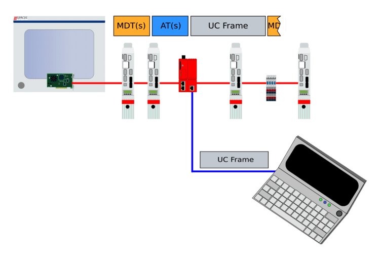
UCC access
UC frames may only enter a Sercos III network through a Sercos III-compliant port. This can be achieved two different ways. One is to employ the unused Sercos III port at the end of a Sercos III network configured in line topology, as shown to the right.
In a network configured in ring topology, the ring can be temporarily broken at any point to also attach a device. Since the redundancy feature of Sercos III will reconfigure the network in a bump-less manner (responding in less than one cycle), no disruption of network transmission will occur. The ring can again be closed after the access is no longer required.
If access is desired in the middle of a line topology (where no free ports are available), or it is undesirable to break a ring topology for extended periods of time, the Sercos III specification permits a device called an “IP-Switch” that can be used to provide access to the UC channel anywhere along the network. IP-Switches supply two Sercos III-compliant ports, and one or more ports for UCC access.
Commercially available UCC Switches block the transmission of Sercos III broadcast telegrams out their non-Sercos III port(s), to prevent flooding of non-Sercos III networks with Sercos III cyclic data.
Common network infrastructure
EtherNet/IP, TC/IP and Sercos devices can be operated via a single Ethernet cable. The highly efficient Sercos telegrams use only a part of the existing bandwidth for real-time data exchange, allowing for the transmission of TC/IP and EtherNet/IP telegrams via the UC channel. For example, an application with 64 drives requires 400 µs and a 2 ms cycle, making 1.6 ms available for TC-IP and EtherNet/IP telegrams.
Because the UC channel sits directly on the Ethernet layer, TC/IP, EtherNet/IP and other Ethernet users can be connected to the network without the need for additional hardware and tunneling of the protocols is not required.
A Sercos master and an EtherNet/IP scanner are required to implement a mixed Sercos and EtherNet/IP network infrastructure. These functionalities can be combined into one device, a dual stack master.
Functional safety support
"Functional safety" is a general term referring to the design of a system that reduces the risk that a hazardous event harmful to humans can occur with a system. The main definition is contained in the international standard IEC 61508. Most industrial networks contain some type of features to conform to functional safety requirements. Rather than define a unique specification for this functional safety, Sercos III Safety is based upon the CIP Safety safety protocol developed by the Open DeviceNet Vendors Association (ODVA). This provides interoperability at the safety level with all networks based upon the Common Industry Protocol (CIP), including DeviceNet and EtherNet/IP.
CIP Safety on Sercos provides for safe data transmission over Sercos III up to SIL 3 (Safety Integrity Level). No additional safety bus is required, as the safety information is sent in addition to the standard data on the Sercos network.
With CIP Safety on Sercos, data is sent on the same medium using the same connections as standard communication. The function of the cross-media CIP Safety protocol is performed by the end units, making it possible to simultaneously operate standard and safety devices in the same network. Reliable communication can take place between all network levels, including peer-to-peer communication and cross-network communication. The master does not necessarily have to be a safety controller. It can also route data without being able to interpret it. This makes it possible for configure the safety network architecture for implementation of safety programmable controllers or peer-to-peer communication between sensors and actuators.
Sercos I/O Profile
The Sercos I/O profile is a device profile for decentralized I/O modules, which can be used for block and modular I/Os. It also supports hybrid devices that combine several functionalities in one single device, e.g., two-axis controller with I/O and master functionality.
An XML-based device and profile description language is specified for I/O device configuration. SDDML (Sercos Device Description Markup Language) describes which profiles are supported by a certain device. SPDML (Sercos Profile Description Markup Language) is used to specify the different profiles on the basis of the Sercos parameter model. Existing standard parameters can be used and manufacturer-specific parameters can also be defined.
Sercos Energy Profile
Sercos Energy is an application layer profile that defines parameters and commands for the reduction of energy consumption in a uniform vendor-independent manner.
Sercos Energy reduces energy consumption in three areas:
In operation, the control reads out parameters of each Sercos Energy component via the Sercos III network, receiving status information and detailed consumption values. Depending on the situation (e.g., scheduled or unscheduled breaks, machine components not needed in the current production process) standardized commands can be issued by the control to switch connected components (drives, I/O, sensors) into energy-saving conditions, up to complete shut-down, reducing their energy consumption.
The profile considers energy-saving conditions for predictable breaks such as lunch periods and plant holidays. At pre-defined times, Sercos Energy components are brought into a standstill condition in order to save energy. Shortly before the end of the interruption, Sercos Energy provides for the re-initialization of components in stand-by condition, to make them available again.
Sercos Energy provides mechanisms for unintended breaks caused by machine errors and missing parts. In these situations, target components can be carefully brought into energy-saving modes while errors are being fixed or during a wait for new parts.
By using intelligent controls, axes and components that are unneeded in ongoing production processes can be switched off and/or target completion times can be adjusted, while still achieving full productivity.
Driver software
Driver software is used to connect a controller to the device logic. A number of basic Sercos drivers are available as open source software from sourceforge.net. These include a common Sercos Master API library, Sercos Internet Protocol Services software and a Sercos UCC Ethernet network driver.
An open source Sercos III Softmaster driver is available. It emulates the Sercos functions, so that a standard Ethernet controller can be used instead of FPGA or ASIC hardware.
A pre-certified CIP Safety on Sercos protocol software is available to equip Sercos and EtherNet/IP devices with the appropriate safe logic up to SIL3.
Certification
Conformance testing verifies that both controls and peripheral devices comply with Sercos standards and are able to operate interoperably in networks with products from multiple vendors. A testing tool, The Sercos Conformizer, can be used to subject a device to a pre-test prior to the formal conformance procedure.