
 | ||
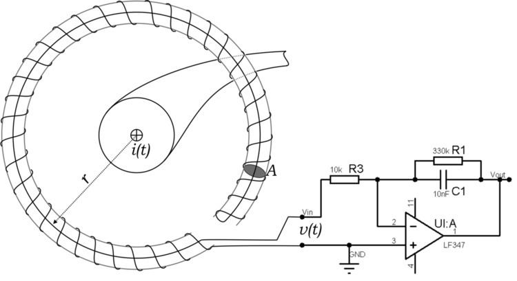
A Rogowski coil, named after Walter Rogowski, is an electrical device for measuring alternating current (AC) or high-speed current pulses. It consists of a helical coil of wire with the lead from one end returning through the centre of the coil to the other end, so that both terminals are at the same end of the coil. The whole assembly is then wrapped around the straight conductor whose current is to be measured. There is no metal (iron) core. The winding density, the diameter of the coil and the rigidity of the winding are critical for preserving immunity to external fields and low sensitivity to the positioning of the measured conductor.
Contents
Since the voltage that is induced in the coil is proportional to the rate of change (derivative) of current in the straight conductor, the output of the Rogowski coil is usually connected to an electrical (or electronic) integrator circuit to provide an output signal that is proportional to the current. Single-chip signal processors with built-in analog to digital converters are often used for this purpose.
Advantages
This type of coil has advantages over other types of current transformers.
Disadvantages
This type of coil also has some disadvantages over other types of current transformers.
Applications
Rogowski coils are used for current monitoring in precision welding systems, arc melting furnaces, or electromagnetic launchers. They are also used in short-circuit testing of electric generators and as sensors in protection systems of electrical plants. Another field of usage is the measurement of harmonic current content, due to their high linearity.
Formulae
The voltage produced by a Rogowski coil is
where
This formula assumes the turns are evenly spaced and that these turns are small relative to the radius of the coil itself.
The output of the Rogowski coil is proportional to the derivative of the wire current. The output is often integrated so the output is proportional to the wire's current:
In practice, an instrument will use a lossy integrator with a time constant much less than the lowest frequency of interest. The lossy integrator will reduce the effects of offset voltages and set the constant of integration to zero.
At high frequencies, the Rogowski coil's inductance will decrease its output.
The inductance of a toroid is
Similar devices
A device similar to the Rogowski coil was described by Arthur Prince Chattock of Bristol University in 1887. Chattock used it to measure magnetic fields rather than currents. The definitive description was given by Walter Rogowski and W. Steinhaus in 1912.
More recently, low-cost current sensors based on the principle of a Rogowski coil have been developed. These sensors share the principles of a Rogowski coil, measuring the rate of change of current using a transformer with no magnetic core. The difference from the traditional Rogowski coil is that the sensor can be manufactured using a planar coil rather than a toroidal coil. In order to reject the influence of conductors outside the sensor's measurement region, these planar Rogowski current sensors use a concentric coil geometry instead of a toroidal geometry to limit the response to external fields. The main advantage of the planar Rogowski current sensor is that the coil winding precision that is a requirement for accuracy can be achieved using low-cost printed circuit board manufacturing.