
 | ||
A quadrupole ion trap is a type of ion trap that uses dynamic electric fields to trap charged particles. They are also called radio frequency (RF) traps or Paul traps in honor of Wolfgang Paul, who invented the device and shared the Nobel Prize in Physics in 1989 for this work. It is used as a component of a mass spectrometer or a trapped ion quantum computer.
Contents
Overview
A charged particle, such as an atomic or molecular ion, feels a force from an electric field. It is not possible to create a static configuration of electric fields that traps the charged particle in all three directions (this restriction is known as Earnshaw's theorem). It is possible, however, to create an average confining force in all three directions by use of electric fields that change in time. To do so, the confining and anti-confining directions are switched at a rate faster than it takes the particle to escape the trap. The traps are also called "radio frequency" traps because the switching rate is often at a radio frequency.
The quadrupole is the simplest electric field geometry used in such traps, though more complicated geometries are possible for specialized devices. The electric fields are generated from electric potentials on metal electrodes. A pure quadrupole is created from hyperbolic electrodes, though cylindrical electrodes are often used for ease of fabrication. Microfabricated ion traps exist where the electrodes lie in a plane with the trapping region above the plane. There are two main classes of traps, depending on whether the oscillating field provides confinement in three or two dimensions. In the two-dimension case (a so-called "linear RF trap"), confinement in the third direction is provided by static electric fields.
Theory
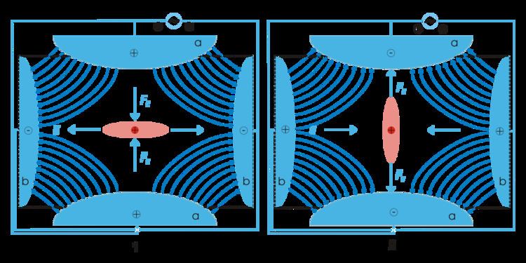
The 3D trap itself generally consists of two hyperbolic metal electrodes with their foci facing each other and a hyperbolic ring electrode halfway between the other two electrodes. The ions are trapped in the space between these three electrodes by AC (oscillating) and DC (static) electric fields. The AC radio frequency voltage oscillates between the two hyperbolic metal end cap electrodes if ion excitation is desired; the driving AC voltage is applied to the ring electrode. The ions are first pulled up and down axially while being pushed in radially. The ions are then pulled out radially and pushed in axially (from the top and bottom). In this way the ions move in a complex motion that generally involves the cloud of ions being long and narrow and then short and wide, back and forth, oscillating between the two states. Since the mid-1980s most 3D traps (Paul traps) have used ~1 mtorr of helium. The use of damping gas and the mass-selective instability mode developed by Stafford et al. led to the first commercial 3D ion traps.
The quadrupole ion trap has two main configurations: the three-dimensional form described above and the linear form made of 4 parallel electrodes. A simplified rectilinear configuration is also used. The advantage of the linear design is its greater storage capacity (in particular of Doppler-cooled ions) and its simplicity, but this leaves a particular constraint on its modeling. The Paul trap is designed to create a saddle-shaped field to trap a charged ion, but with a quadrupole, this saddle-shaped electric field cannot be rotated about an ion in the centre. It can only 'flap' the field up and down. For this reason, the motions of a single ion in the trap are described by Mathieu Equations, which can only be solved numerically by computer simulations.
The intuitive explanation and lowest order approximation is the same as strong focusing in accelerator physics. Since the field affects the acceleration, the position lags behind (to lowest order by half a period). So the particles are at defocused positions when the field is focusing and vice versa. Being farther from center, they experience a stronger field when the field is focusing than when it is defocusing.
Equations of motion
Ions in a quadrupole field experience restoring forces that drive them back toward the center of the trap. The motion of the ions in the field is described by solutions to the Mathieu equation. When written for ion motion in a trap, the equation is
where
Substituting Equation 2 into the Mathieu Equation 1 yields
Reorganizing terms shows us that
By Newton's laws of motion, the above equation represents the force on the ion. This equation can be exactly solved using Floquet theorem or the standard techniques of multiple scale analysis. The particle dynamics and time averaged density of charged particles in a Paul trap can also be obtained by the concept of ponderomotive force.
The forces in each dimension are not coupled, thus the force acting on an ion in, for example, the x dimension is
Here,
where
For an ion trap,
Transforming Equation 5 into a cylindrical coordinate system with
The applied electric potential is a combination of RF and DC given by
where
Substituting Equation 7 into Equation 5 with
Substituting Equation 8 into Equation 4 leads to
Comparing terms on the right hand side of Equation 1 and Equation 9 leads to
and
Further
and
The trapping of ions can be understood in terms of stability regions in
Linear ion trap
The linear ion trap uses a set of quadrupole rods to confine ions radially and a static electrical potential on-end electrodes to confine the ions axially. The linear form of the trap can be used as a selective mass filter, or as an actual trap by creating a potential well for the ions along the axis of the electrodes. Advantages of the linear trap design are increased ion storage capacity, faster scan times, and simplicity of construction (although quadrupole rod alignment is critical, adding a quality control constraint to their production. This constraint is additionally present in the machining requirements of the 3D trap).
Cylindrical ion trap
Ion traps with a cylindrical rather than a hyperbolic ring electrode have been developed and microfabricated in arrays to develop miniature mass spectrometers for chemical detection in medical diagnosis and other fields.
Combined radio frequency trap
A combined radio frequency trap is a combination of a Paul ion trap and a Penning trap. One of the main bottlenecks of a QIT is that it can confine only single-charged species or multiple species with similar masses. But in certain applications like antihydrogen production it is important to confine two species of charged particles of widely varying masses. To achieve this objective, a uniform magnetic field is added in the axial direction of the QIT.