
 | ||
Phosphor thermometry is an optical method for surface temperature measurement. The method exploits luminescence emitted by phosphor material. Phosphors are fine white or pastel-colored inorganic powders which may be stimulated by any of a variety of means to luminesce, i.e. emit light. Certain characteristics of the emitted light change with temperature, including brightness, color, and afterglow duration. The latter is most commonly used for temperature measurement.
Contents
Time dependence of luminescence
Typically a short duration ultraviolet lamp or laser source illuminates the phosphor coating which in turn luminesces visibly. When the illuminating source ceases, the luminescence will persist for a characteristic time, steadily decreasing. The time required for the brightness to decrease to 1/e of its original value is known as the decay time or lifetime and signified as
The intensity, I of the luminescence commonly decays exponentially as:
Where I0 is the initial intensity (or amplitude).
The method is also referred to as fluorescence thermometry since it is also the case that similar materials in the form of glass, crystals, or even optical fibers will fluoresce and may be used as temperature sensors. Fiberoptic amplifiers are based on optical fibers doped with rare earths. Such fibers are useful for temperature measurement.
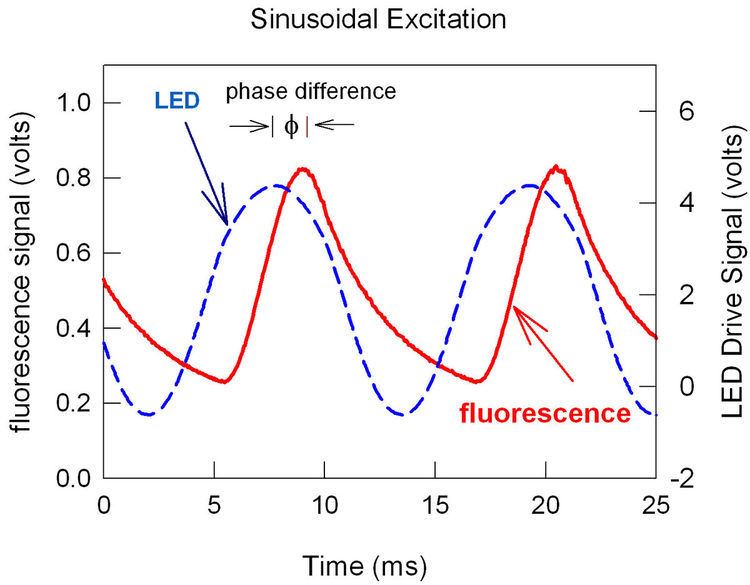
If the excitation source is periodic rather than pulsed, then the time response of the luminescence is correspondingly different. For instance, there is a phase difference between a sinusoidally varying light emitting diode (LED) signal of frequency f and the fluorescence that results (see figure). The phase difference varies with decay time and hence temperature as:
Temperature dependence of emission lines: intensity ratio
The second method of temperature detection is based on intensity ratios of two separate emission lines; the change in coating temperature is reflected by the change of the phosphorescence spectrum. This method enables surface temperature distributions to be measured. The intensity ratio method has the advantage that polluted optics has little effect on the measurement as it compares ratios between emission lines. The emission lines are equally affected by 'dirty' surfaces or optics.
Temperature dependence
Several observations are pertinent to the figure on the right:
There are further parameters influencing the luminescence of thermographic phosphors, e.g. the excitation energy, the dopant concentration or the composition or the absolute pressure of the surrounding gas phase. Therefore, care has to be taken in order to keep constant these parameters for all measurements.
Thermographic phosphor application in a thermal barrier coating
A thermal barrier coating (TBC) allows gas turbine components to survive higher temperatures in the hot section of engines, while having acceptable life times. These coatings are thin ceramic coatings (several hundred micrometers) usually based on oxide materials.
Early works considered the integration of luminescent materials as erosion sensors in TBCs. The notion of a "thermal barrier sensor coating" (sensor TBC) for temperature detection was introduced in 1998. Instead of applying a phosphor layer on the surface where the temperature needs to be measured, it was proposed to locally modify the composition of the TBC so that it acts as a thermographic phosphor as well as a protective thermal barrier. This dual functional material enables surface temperature measurement but also could provide a means to measure temperature within the TBC and at the metal/topcoat interface, hence enabling the manufacturing of an integrated heat flux gauge. First results on yttria-stabilized zirconia co-doped with europia (YSZ:Eu) powders were published in 2000. They also demonstrated sub-surface measurements looking through a 50 μm undoped YSZ layer and detecting the phosphorescence of a thin (10 µm) YSZ:Eu layer (bi-layer system) underneath using the ESAVD technique to produce the coating. The first results on electron beam physical vapour deposition of TBCs were published in 2001. The coating tested was a monolayer coating of standard YSZ co-doped with dysprosia (YSZ:Dy). First work on industrial atmospheric plasma sprayed (APS) sensor coating systems commenced around 2002 and was published in 2005. They demonstrated the capabilities of APS sensor coatings for in-situ two-dimensional temperature measurements in burner rigs using a high speed camera system. Further, temperature measurement capabilities of APS sensor coatings were demonstrated beyond 1400 °C. Results on multilayer sensing TBCs, enabling simultaneous temperature measurements below and on the surface of the coating, were reported. Such a multilayer coating could also be used as a heat flux gauge in order to monitor the thermal gradient and also to determine the heat flux through the thickness of the TBC under realistic service conditions.
Applications for thermographic phosphors in TBCs
While the previously mentioned methods are focusing on the temperature detection, the inclusion of phosphorescent materials into the thermal barrier coating can also work as a micro probe to detect the aging mechanisms or changes to other physical parameters that affect the local atomic surroundings of the optical active ion. Detection was demonstrated of hot corrosion processes in YSZ due to vanadium attack.
Videos: application of thermographic phosphors
Phosphorescence sensor coating for online temperature detection