
Instrument Type Communications Mission duration 90 days | Function Laser Communications Began operations 18 April 2014 | |
 | ||
Operator Jet Propulsion Laboratory Manufacturer Jet Propulsion Laboratory | ||
Optical PAyload for Lasercomm Science (OPALS) is a spacecraft communication instrument developed at the Jet Propulsion Laboratory that was tested on the International Space Station (ISS) from 18 April 2014 to 17 July 2014 to demonstrate the technology for laser communications systems between spacecraft and ground stations.
Contents
The purpose of OPALS is to do research into replacing traditional radio-frequency (RF) communications which are currently used on spacecraft. This will allow spacecraft to increase the rate at which data is downlinked by 10 to 100 times. It also will have less error than RF communication.
It launched from Cape Canaveral to the ISS on 18 April 2014 on a Falcon 9 SpaceX CRS-3 Dragon capsule resupply.
Science objectives
The goal of the OPALS mission was to demonstrate a downlink of a short video from space using laser communication. In doing so, the following was learned:
Mission architecture
Communications and commands were sent to the flight system via the Mission Operations System (MOS), which is a process developed by the OPALS team. When the team wanted to execute a laser downlink, it went as follows
- The information starts at the flight MOS located the mission control at JPL, where communications with the flight system is planned
- Information is sent to the Huntsville Operations Support Center (HOSC) at the Marshall Space Flight Center where it is sent via RF to the Tracking Data and Relay Services System (TDRSS), which is a communications satellite array
- The TDRSS sends the information to the ISS and the flight system, again via RF
- The flight system executes the laser downlink, which is received by the Optical Communications Telescope Laboratory (OCTL) in Wrightwood, California, where the OPALS ground system is located
- The information is finally given to the principal investigator of the OPALS mission for the team to analyze
This process is executed in a matter of seconds. In the case of communications that are not laser transmission (e.g. system health checks), the architecture is much the same. The uplink is the same, following steps 1-3. The downlink instead of going down to the OCTL goes through the same path as the uplink, except backwards. Just like the uplink, all the communications are via RF.
Although most downlinks went through the OCTL, some went through other ground stations, including the German Aerospace Center's (DLR) optical ground station in Oberpfaffenhofen, Germany and the European Space Agency's ground station in Mount Teide, Tenerife, Canary Islands.
Systems
The OPALS has two hardware systems: the flight system, which sends the laser downlinks from the ISS, and the ground system, which helps the flight system know where to point and receives its downlinks.
Flight System
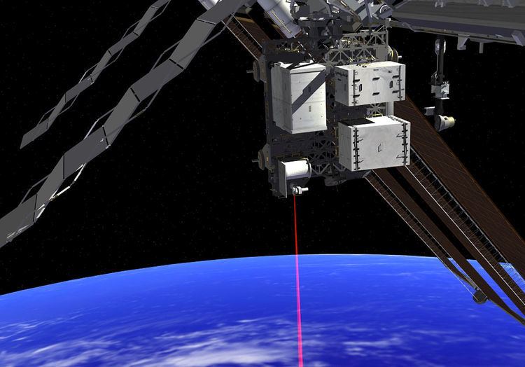
The flight system (depicted on the right) has three major parts, the sealed container, the optical gimbal transceiver, and the Flight Releasable Attachment Mechanism (FRAM).
The sealed container houses the electronics, avionics, the communications laser, and a custom power board pressurized to 1 atmosphere with air to keep the electronics cool. The laser uses a light wavelength of 1,550 nanometers with 2.5 watts of power and has a 2.2 centimeter diameter aperture. The laser was routed through fiber to the gimbal transceiver where it was transmitted with 1.5 milliradian beam divergence.
The optical gimbal transceiver holds the uplink camera and the laser collimator on a 2-axis gimbal. Due to laser safety considerations, the gimbal may not shine on anything on the ISS. To avoid this, the gimbal is designed with mechanical stops and electromechanical limit switches so that its field of regard (the area where it can point) is limited to 36° wide in elevation and 106° in azimuth, where the azimuthal axis is generally in the direction of motion of the ISS. Because of the gimbal field of regard geometry, the flight system can only perform downlinks when the ISS is north of the ground station.
Because of the fast-changing viewing geometry during passes, the direction in which the gimbal must point throughout the pass must be pre-computed. The list of directions for the gimbal to point was calculated based on the ISS GPS state vector and attitude quaternion. The need for this list to be accurate was very important because of error in ISS orientation predictions and because the gimbal lacked any encoders, so all gimbal movement had to be done through dead reckoning. Once the flight system detects the beacon from the ground system, it tracks beacon with the gimbal.
The FRAM is the interface between OPALS and the ISS. It was not designed by the OPALS team, but was an existing part designed by the ISS team at Johnson Space Center.
Ground System
The ground system is what receives the signal from the flight system's laser downlinks. Most frequently, the Optical Communications Telescope Laboratory (OCTL) in Wrightwood, California was used as the ground station, but other international stations were used as well. The observatory has a 1-meter mirror through which all of the laser downlinks are performed. The telescope has the capability of tracking objects that are in Low Earth Orbit. The ground system's function is to indicate to the flight system where to point the laser and then to receive that signal. It indicates where the laser must point by illuminating the ISS with a 976 nanometer laser. Signal is received through a 3 nanometer bandpass 1550 nanometer spectral filter in front of an indium gallium arsenide acquisition camera and an avalanche photodiode detector, which makes it so that the collected image isn't backscattered (which is headlights being reflected by fog) by sunlight during day passes.
Results
OPALS attempted 26 downlinks, of which 18 were successful. Half of the successes were attempted at night, and half during the day. Below is a list of several downlink attempts.
Despite many downlinks being considered a failure, some of those failures were able to send the entire data package, since downlink data consisted of the same data package repeated many times.
Generally, downlinks were more successful in the day than in the night. Downlinks also suffered in the event of cloudy weather, although on some occasions it was able to reacquire the signal. Some difficulty was found with downlinks to high-latitude ground stations, like DLR.