
 | ||
The theory of micro-mechanics of failure aims to explain the failure of continuous fiber reinforced composites by micro-scale analysis of stresses within each constituent material (such as fiber and matrix), and of the stresses at the interfaces between those constituents, calculated from the macro stresses at the ply level.
Contents
- Basic concepts
- Unit cell model
- Stress amplification factor SAF
- Fiber failure criterion
- Matrix failure criterion
- Interface failure criterion
- Hashins Failure Criteria
- References
As a completely mechanics-based failure theory, the theory is expected to provide more accurate analyses than those obtained with phenomenological models such as Tsai-Wu and Hashin failure criteria, being able to distinguish the critical constituent in the critical ply in a composite laminate.
Basic concepts
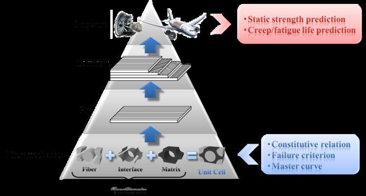
The basic concept of the micro-mechanics of failure (MMF) theory is to perform a hierarchy of micromechanical analyses, starting from mechanical behavior of constituents (the fiber, the matrix, and the interface), then going on to the mechanical behavior of a ply, of a laminate, and eventually of an entire structure.
At the constituent level, three elements are required to fully characterize each constituent:
The constituents and a unidirectional lamina are linked via a proper micromechanical model, so that ply properties can be derived from constituent properties, and on the other hand, micro stresses at the constituent level can be calculated from macro stresses at the ply level.
Unit cell model
Starting from the constituent level, it is necessary to devise a proper method to organize all three constituents such that the microstructure of a UD lamina is well-described. In reality, all fibers in a UD ply are aligned longitudinally; however, in the cross-sectional view, the distribution of fibers is random, and there is no distinguishable regular pattern in which fibers are arrayed. To avoid such a complication cause by the random arrangement of fibers, an idealization of the fiber arrangement in a UD lamina is performed, and the result is the regular fiber packing pattern. Two regular fiber packing patterns are considered: the square array and the hexagonal array. Either array can be viewed as a repetition of a single element, named unit cell or representative volume element (RVE), which consists of all three constituents. With periodical boundary conditions applied, a unit cell is able to respond to external loadings in the same way that the whole array does. Therefore, a unit cell model is sufficient in representing the microstructure of a UD ply.
Stress amplification factor (SAF)
Stress distribution at the laminate level due to external loadings applied to the structure can be acquired using finite element analysis (FEA). Stresses at the ply level can be obtained through transformation of laminate stresses from laminate coordinate system to ply coordinate system. To further calculate micro stresses at the constituent level, the unit cell model is employed. Micro stresses
Here
Fiber failure criterion
Fiber is taken as transversely isotropic, and there are two alternative failure criteria for it: a simple maximum stress criterion and a quadratic failure criterion extended from Tsai-Wu failure criterion:
The Coefficients involved in the quadratic failure criterion are defined as follows:
where
Stresses used in two preceding criteria should be micro stresses in the fiber, expressed in such a coordinate system that 1-direction signifies the longitudinal direction of fiber.
Matrix failure criterion
The polymeric matrix is assumed to be isotropic and exhibits a higher strength under uniaxial compression than under uniaxial tension. A modified version of von Mises failure criterion suggested by Christensen is adopted for the matrix:
Here
Interface failure criterion
The fiber-matrix interface features traction-separation behavior, and the failure criterion dedicated to it takes the following form:
where
Hashin’s Failure Criteria
These are interacting failure criteria where more than one stress components have been used to evaluate the different failure modes. These criteria were originally developed for unidirectional polymeric composites, and hence, applications to other type of laminates and non-polymeric composites have significant approximations. Usually Hashin criteria are implemented within two-dimensional classical lamination approach for point stress calculations with ply discounting as the material degradation model. Failure indices for Hashin criteria are related to fibre and matrix failures and involve four failure modes. The criteria are extended to three-dimensional problems where the maximum stress criteria are used for transverse normal stress component. The failure modes included in Hashin’s criteria are as follows.
- Tensile fibre failure for σ11 ≥ 0
- Compressive fibre failure for σ11 < 0
- Tensile matrix failure for σ22 + σ33 > 0
- Compressive matrix failure for σ22 + σ33 < 0
- Interlaminar tensile failure for σ33 > 0
- Interlaminar compression failure for σ33 < 0
where, σij denote the stress components and the tensile and compressive allowable strengths for lamina are denoted by subscripts T and C, respectively. XT, YT, ZT denotes the allowable tensile strengths in three respective material directions. Similarly, XC, YC, ZC denotes the allowable compressive strengths in three respective material directions. Further, S12, S13 and S23 denote allowable shear strengths in the respective principal material directions.
Endeavors have been made to incorporate MMF with multiple progressive damage models and fatigue models for strength and life prediction of composite structures subjected to static or dynamic loadings.