
 | ||
Logic redundancy occurs in a digital gate network containing circuitry that does not affect the static logic function. There are several reasons why logic redundancy may exist. One reason is that it may have been added deliberately to suppress transient glitches (thus causing a race condition) in the output signals by having two or more product terms overlap with a third one.
Contents
Consider the following equation:
The third product term
Another reason for logic redundancy is poor design practices which unintentionally result in logically redundantly terms. This causes an unnecessary increase in network complexity, and possibly hampering the ability to test manufactured designs using traditional test methods (single stuck-at fault models). (Note: testing might be possible using IDDQ models.)
Removing logic redundancy
Logic redundancy is, in general, not desired. Redundancy, by definition, requires extra parts (in this case: logical terms) which raises the cost of implementation (either actual cost of physical parts or CPU time to process). Logic redundancy can be removed by several well-known techniques, such as Karnaugh maps, the Quine–McCluskey algorithm, and the heuristic computer method.
Adding logic redundancy
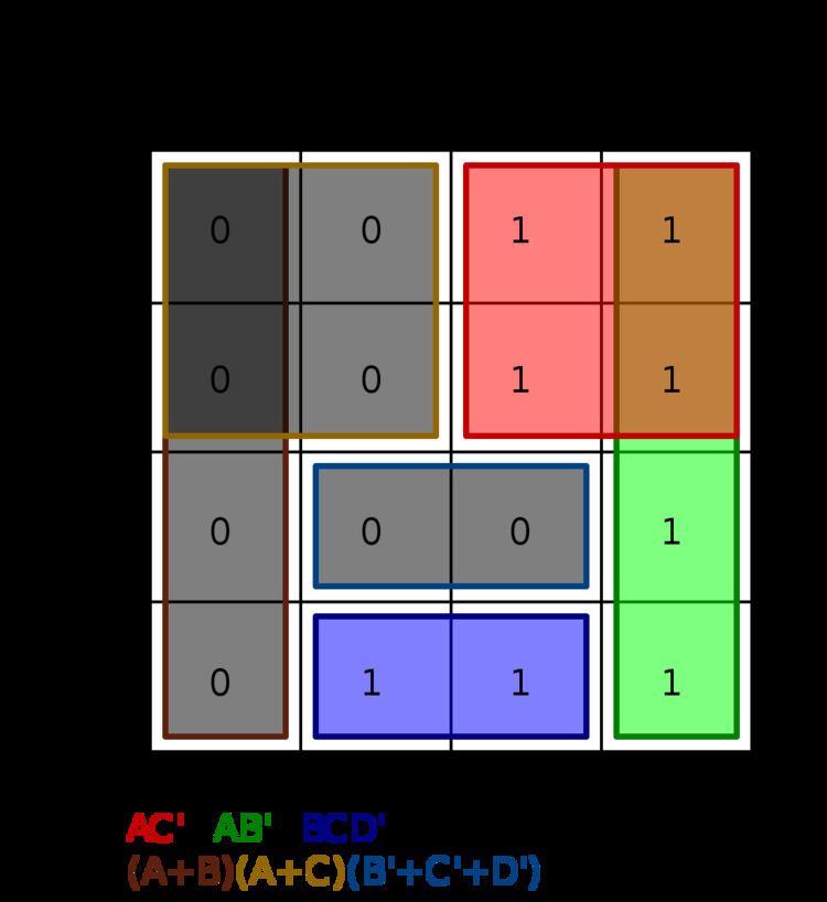
In some cases it may be desirable to add logic redundancy. One of those cases is to avoid race conditions whereby an output can fluctuate because different terms are "racing" to turn off and on. To explain this in more concrete terms the Karnaugh map to the right shows the minterms and maxterms for the following function:
The boxes represent the minimal AND/OR terms needed to implement this function:
The k-map visually shows where race conditions occur in the minimal expression by having gaps between minterms or gaps between maxterms. For example, the gap between the blue and green rectangles. If the input
The race condition is removed by adding in logic redundancy, which is contrary to the aims of using a k-map in the first place. Both minterm race conditions are covered by addition of the yellow term
In this case, the addition of logic redundancy has stabilized the output to avoid output fluctuations because terms are racing each other to change state.