
 | ||
Light sheet fluorescence microscopy (LSFM) is a fluorescence microscopy technique with an intermediate optical resolution, but good optical sectioning capabilities and high speed. In contrast to epifluorescence microscopy only a thin slice (usually a few hundred nanometers to a few micrometers) of the sample is illuminated perpendicularly to the direction of observation. For illumination, a laser light-sheet is used, i.e. a laser beam which is focused only in one direction (e.g. using a cylindrical lens). A second method uses a circular beam scanned in one direction to create the lightsheet. As only the actually observed section is illuminated, this method reduces the photodamage and stress induced on a living sample. Also the good optical sectioning capability reduces the background signal and thus creates images with higher contrast, comparable to confocal microscopy. Because LSFM scans samples by using a plane of light instead of a point (as in confocal microscopy), it can acquire images at speeds 100 to 1000 times faster than those offered by point-scanning methods.
Contents
- Basic setup
- Extensions of the basic LSFM idea
- Sample mounting
- Typical imaging modes
- Power of resolution
- Stripe artifacts
- History
- Application
- References
This method is used in cell biology and for microscopy of intact, often chemically cleared, organs, embryos, and organisms.
Starting in 1994, LSFM was developed as orthogonal plane fluorescence optical sectioning microscopy or tomography (OPFOS) mainly for large samples and later as the selective/single plane illumination microscopy (SPIM) also with sub-cellular resolution. This introduced an illumination scheme into fluorescence microscopy, which has already been used successfully for dark field microscopy under the name ultramicroscopy.
Basic setup
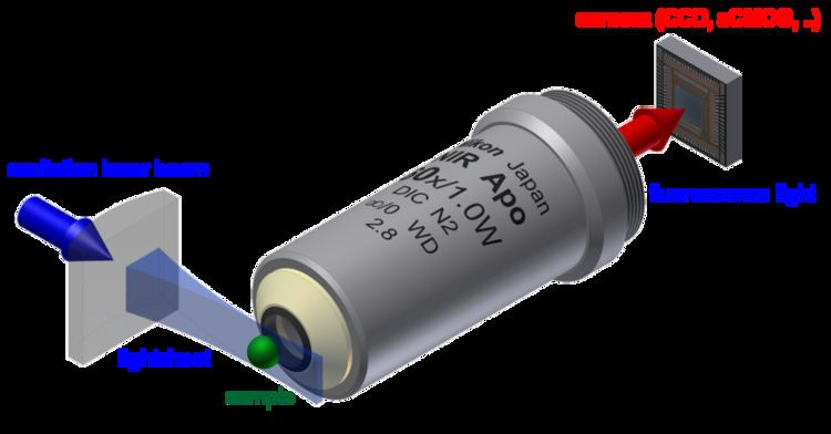
In this type of microscopy, the illumination is done perpendicularly to the direction of observation (see schematic image at the top of the article). The expanded beam of a laser is focused in only one direction by a cylindrical lens, or by a combination of a cylindrical lens and a microscope objective as the latter is available in better optical quality and with higher numerical aperture than the first. This way a thin sheet of light or lightsheet is created in the focal region that can be used to excite fluorescence only in a thin slice (usually a few micrometers thin) of the sample.
The fluorescence light emitted from the lightsheet is then collected perpendicularly with a standard microscope objective and projected onto an imaging sensor (usually a CCD, electron multiplying CCD or CMOS camera). In order to let enough space for the excitation optics/lightsheet an observation objective with high working distance is used. In most LSFMs the detection objective and sometimes also the excitation objective are fully immersed in the sample buffer, so usually the sample and excitation/detection optics are embedded into a buffer-filled sample chamber, which can also be used to control the environmental conditions (temperature, carbon dioxide level ...) during the measurement. The sample mounting in LSFM is described below in more detail.
As both the excitation lightsheet and the focal plane of the detection optics have to coincide to form an image, focusing different parts of the sample can not be done by translating the detection objective, but usually the whole sample is translated and rotated instead.
Extensions of the basic LSFM idea
In recent years, several extensions to this scheme have been developed:
Sample mounting
The separation of the illumination and detection beampaths in LSFM (except in oblique plane microscopy) creates a need for specialized sample mounting methods. To date most LSFMs are built in such a way that the illumination and detection beampath lie in a horizontal plane (see illustrations above), thus the sample is usually hanging from the top into the sample chamber or is resting on a vertical support inside the sample chamber. Several methods have been developed to mount all sorts of samples:
Some LSFMs have been developed where the sample is mounted as in standard microscopy (e.g. cells grow horizontally on the bottom of a petri dish) and the excitation and detection optics are constructed in an upright plane from above. This also allows combining a LSFM with a standard inverted microscope and avoids the requirement for specialized sample mounting procedures.
Typical imaging modes
Most LSFMs are used to produce 3D images of the sample by moving the sample through the image plane. If the sample is larger than the field of view of the image sensor, the sample also has to be shifted laterally. An alternative approach is to move the image plane through the sample to create the image stack.
Long experiments can be carried out, for example with stacks is recorded every 10 s–10 min over the timespan of days. This allows study of changes over time in 3D, or so-called 4D microscopy.
After the image acquisition the different image stacks are registered to form one single 3D dataset. Multiple views of the sample can be collected, either by interchanging the roles of the objectives or by rotating the sample. Having multiple views can yield more information than a single stack; for example occlusion of some parts of the sample may be overcome. Multiple views also improves 3D image resolution by overcoming poor axial resolution as described below.
Some studies also use a SPIM to image only one slice of the sample, but at much higher temporal resolution. This allows e.g. to observe the beating heart of a zebra fish embryo in real-time. Together with fast translation stages for the sample a high-speed 3D particle tracking has been implemented.
Power of resolution
The lateral resolution of a SPIM is comparable to that of a standard (epi) fluorescence microscope, as it is determined fully by the detection objective and the wavelength of the detected light (see Abbe limit). E.g. for detection in the green spectral region around 525 nm, a resolution of 250–500 nm can be reached. The axial resolution is worse than the lateral (about a factor of 4), but it can be improved by using a thinner lightsheet in which case nearly isotropic resolution is possible. Thinner light sheets are either thin only in a small region (for Gaussian beams) or else specialized beam profiles such as Bessel beams must be used (besides added complexity, such schemes add side lobes which can be detrimental ). Alternatively, isotropic resolution can be achieved by computationally combining 3D image stacks taken from the same sample under different angles. Then the depth-resolution information lacking in one stack is supplied from another stack; for example with two orthogonal stacks the (poor-resolution) axial direction in one stack is a (high-resolution) lateral direction in the other stack.
The lateral resolution of LSFM can be improved beyond the Abbe limit, by using super resolution microscopy techniques, e.g. with using the fact, that single fluorophores can be located with much higher spatial precision than the nominal resolution of the used optical system (see stochastic localization microscopy techniques). Also structured illumination techniques have been applied to further improve the optical sectioning capacity of LSFM.
Stripe artifacts
As the illumination typically penetrates the sample from one side, obstacles lying in the way of the lightsheet can disturb its quality by scattering and/or absorbing the light. This typically leads to dark and bright stripes in the images. If parts of the samples have a significantly higher refractive index (e.g. lipid vesicles in cells), they can also lead to a focussing effect resulting in bright stripes behind these structures. To overcome this artifact, the lightsheets can e.g. be "pivoting". That means that the lightsheet's direction of incidence is changed rapidly (~1 kHz rate) by a few degrees (~10°), so light also hits the regions behind the obstacles. Illumination can also be performed with two (pivoted) lightsheets (see above) to further reduce these artifacts. Alternatively, an algorithm called VSNR (Variational Stationary Noise Remover) has been developed and is available as a free Fiji plugin.
History
At the beginning of the 20th century, R. A. Zsigmondy introduced the ultramicroscope as a new illumination scheme into dark-field microscopy. Here sunlight or a white lamp is used to illuminate a precision slit. The slit is then imaged by a condensor lens into the sample to form a lightsheet. Scattering (sub-diffractive) particles can be observed perpendicularly with a microscope. This setup allowed the observation of particles with sizes smaller than the microscope's resolution and led to a Nobel prize for Zsigmondy in 1925.
The first application of this illumination scheme for fluorescence microscopy was published in 1993 by Voie et al. under the name orthogonal-plane fluorescence optical sectioning (OPFOS). for imaging of the internal structure of the cochlea. The resolution at that time was limited to 10 µm laterally and 26 µm longitudinally but at a sample size in the millimeter range. The OPFOS microscope used a simple cylindrical lens for illumination. Further development and improvement of the SPIM started in 2004. After this publication by Huisken et al. the technique found wide application and is still adapted to new measurement situations today (see above). Since 2010 a first ultramicroscope with fluorescence excitation and limited resolution and since 2012 a first SPIM are available commercially. A good overview about the development of SPIM is given in ref. During 2012 also open source projects have started to appear that freely publish complete construction plans for LSFMs and also the required software suites.
Application
SPIM/LSFM is often used in developmental biology, where it enables long-time (several days) observations of embryonic development (even with full lineage tree reconstruction). SPIM can also be combined with techniques, like fluorescence correlation spectroscopy to allow spatially resolved mobility measurements of fluorescing particles (e.g. fluorescent beads, quantum dots or fluorescently labeled proteins) inside living biological samples.