
 | ||
An instrument approach, or instrument approach procedure (IAP), is a series of predetermined maneuvers for the orderly transfer of an aircraft under instrument flight conditions from the beginning of the initial approach to a landing or to a point from which a landing may be made visually. These approaches are approved in the United States by the FAA or the United States Department of Defense for the military. The ICAO defines an instrument approach as a series of predetermined maneuvers by reference to flight instruments with specific protection from obstacles from the initial approach fix, or where applicable, from the beginning of a defined arrival route to a point from which a landing can be completed and thereafter, if landing is not completed, to a position at which holding or enroute obstacle clearance criteria apply.
Contents
- Instrument approach segments
- Types of approaches
- Visual approach
- Contact approach
- Charted visual flight procedures CVFP
- RNAV approach
- ILS approach
- VOR approach
- NDB approach
- Radar approach
- Localizer approach
- Simplified directional facility SDF approach
- Non precision approaches and systems
- Precision approaches and systems
- Decision height or altitude
- Minimum descent altitude MDA
- Straight in approach IFR
- Course reversal procedure
- Circle to land maneuver
- Sidestep maneuver
- Rate of descent formula
- Airport requirements
- Additional reading
- References
There are three types of IAPs: precision approach (PA), approach with vertical guidance (APV), and nonprecision approach (NPA). A PA uses a navigation system that provides course and glidepath deviation. Examples include precision approach radar (PAR), instrument landing system (ILS), and GBAS landing system (GLS). An APV also uses a navigation system for course and glidepath deviation, just not to the same standards as a PA. Examples include baro-VNAV, localizer type directional aid (LDA) with glidepath, LNAV/VNAV and LPV. An NPA uses a navigation system for course deviation but does not provide glidepath information. These approaches include VOR, NDB and LNAV. NPAs are flown to a minimum descent altitude (MDA).
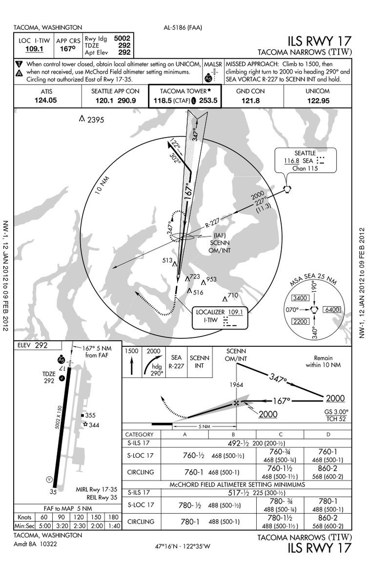
IAP charts are aeronautical charts that portray the aeronautical data that is required to execute an instrument approach to an airport. Besides depicting topographic features, hazards and obstructions, they depict the procedures and airport diagram. Each procedure chart uses a specific type of electronic navigation system such as an NDB, TACAN, VOR, ILS/MLS and RNAV. The chart name reflects the primary navigational aid (NAVAID), if there is more than one straight-in procedure or if it is just a circling-only procedure. A communication strip on the chart lists frequencies in the order they are used. Minimum, maximum and mandatory altitudes are depicted in addition to the minimum safe altitude (MSA) for emergencies. A cross depicts the final approach fix (FAF) altitude on NPAs while a lightning bolt does the same for PAs. NPAs depict the MDA while a PA shows both the decision altitude (DA) and decision height (DH). Finally, the chart depicts the missed approach procedures in plan and profile view, besides listing the steps in sequence.
Before satellite navigation was available for civilian aviation, the requirement for large land-based navigation aid (NAVAID) facilities generally limited the use of instrument approaches to land-based (i.e. asphalt, gravel, turf, ice) runways (and those on aircraft carriers). GNSS technology allows, at least theoretically, to create instrument approaches to any point on the Earth's surface (whether on land or water); consequently, there are nowadays examples of water aerodromes (such as Rangeley Lake Seaplane Base in Maine, United States) that have GNSS-based approaches.
Instrument approach segments
An instrument approach procedure may contain up to five separate segments, which depict course, distance, and minimum altitude. These segments are
When an aircraft is under radar control, air traffic control (ATC) may replace some or all of these phases of the approach with radar vectors (ICAO radar vectoring is the provision of navigational guidance to aircraft in the form of specific headings, based on the use of radar). ATC will use an imaginary "approach gate" when vectoring aircraft to the final approach course. This gate will be 1 nautical mile (NM) from the FAF and at least 5 NM from the landing threshold. Outside radar environments, the instrument approach starts at the IAF.
Types of approaches
Though ground-based NAVAID approaches still exist, the FAA is transitioning to approaches which are satellite-based (RNAV). Additionally, in lieu of the published approach procedure, a flight may continue as an IFR flight to landing while increasing the efficiency of the arrival with either a contact or visual approach.
Visual approach
A visual approach is an ATC authorization for an aircraft on an IFR flight plan to proceed visually to the airport of intended landing; it is not an instrument approach procedure.
A visual approach may be requested by the pilot or offered by ATC. Visual approaches are possible when weather conditions permit continuous visual contact with the destination airport. They are issued in such weather conditions in order to expedite handling of IFR traffic. The ceiling must be reported or expected to be at least 1000 feet AGL (above ground level) and the visibility is at least 3 SM (statute miles).
A pilot may accept a visual approach clearance as soon as the pilot has the destination airport in sight. According to ICAO Doc. 4444, it is enough for a pilot to see the terrain to accept a visual approach. The point is that if a pilot is familiar with the terrain in the vicinity of the airfield he/she may easily find the way to the airport having the surface in sight. ATC must ensure that weather conditions at the airport are above certain minima (in the U.S., a ceiling of 1000 feet AGL or greater and visibility of at least 3 statute miles) before issuing the clearance. According to ICAO Doc. 4444, it is enough if the pilot reports that in his/her opinion the weather conditions allow a visual approach to be made. In general the ATC gives the information about the weather but it's the pilot who makes a decision if the weather is suitable for landing. Once the pilot has accepted the clearance, he/she assumes responsibility for separation and wake turbulence avoidance and may navigate as necessary to complete the approach visually. According to ICAO Doc. 4444, ATC continues to provide separation between the aircraft making a visual approach and other arriving and departing aircraft. The pilot may get responsible for the separation with preceding aircraft in case he/she has the preceding aircraft in sight and is instructed so by ATC.
In the United States, it is required that an aircraft have the airport, the runway, or the preceding aircraft in sight. It is not enough to have the terrain in sight (see #Contact approach).
When a pilot accepts a visual approach, the pilot accepts responsibility for establishing a safe landing interval behind the preceding aircraft, as well as responsibility for wake-turbulence avoidance, and to remain clear of clouds.
Contact approach
A contact approach that may be asked for by the pilot (but not offered by ATC) in which the pilot has 1 SM flight visibility and is clear of clouds and is expected to be able to maintain those conditions all the way to the airport. Obstruction clearances and VFR traffic avoidance become the pilot's responsibility.
Charted visual flight procedures (CVFP)
A visual approach that has a specified route the aircraft is to follow to the airport. Pilots must have a charted visual landmark or a preceding aircraft in sight, and weather must be at or above the published minimums. Pilots are responsible for maintaining a safe approach interval and wake turbulence separation.
RNAV approach
These approaches include both ground-based and satellite-based systems and include criteria for terminal areas (TAAs), basic approach criteria, and final approach criteria. The TAA is a transition from the en route structure to the terminal environment which provides minimum altitudes for obstacle clearance. The TAA is a "T" or "basic T" design with left and right base leg IAFs on initial approach segments perpendicular to the intermediate approach segment where there is a dual purpose IF/IAF for a straight-in procedure (no procedure turn [NoPT]), or hold-in-lieu-of procedure-turn (HILO) course reversal. The base leg IAFs is 3 to 6 NM from the IF/IAF. The basic-T is aligned with the runway centerline, with the IF 5 NM from the FAF, and the FAF is 5 NM from the threshold.
ILS approach
These are the most precise and accurate approaches. A runway with an ILS can accommodate 29 arrivals per hour.‹See TfD› ILS systems on two or three runways increase capacity with parallel (dependent) ILS, simultaneous parallel (independent) ILS, precision runway monitor (PRM), and converging ILS approaches. ILS approaches have three classifications, CAT I, CAT II, and CAT III. CAT II and CAT III require additional certification for operators, pilots, aircraft and equipment, with CAT III used mainly by air carriers and the military. Simultaneous parallel approaches require runway centerlines to be between 4,300 and 9,000 feet apart, plus a "dedicated final monitor controller" to monitor aircraft separation. Simultaneous close parallel (independent) PRM approaches must have runways separation to be between 3,400 and 4,300 feet. Simultaneous offset instrument approaches (SOIAs) apply to runways separated by 750–3,000 feet. A SOIA uses an ILS/PRM on one runway and an LDA/PRM with glideslope for the other.
VOR approach
These approaches use VOR facilities on and off the airport and may be supplemented with DME and TACAN.
NDB approach
These approaches use NDB facilities on and off the airport and may be supplemented with a DME. These approaches are gradually being phased out.
Radar approach
This will be either a precision approach radar (PAR) or an airport surveillance radar (ASR) approach. Information is published in tabular form. The PAR provides vertical and lateral guidance plus range. The ASR only provides heading and range information.
Localizer approach
These approaches include a localizer approach, localizer/DME approach, localizer back course approach, and a localizer-type directional aid (LDA). In cases where an ILS is installed, a back course may be available in conjunction with the localizer. Reverse sensing occurs on the back course using standard VOR equipment. With a horizontal situation indicator (HSI) system, reverse sensing is eliminated if it is set appropriately to the front course.
Simplified directional facility (SDF) approach
This type of approach is similar to the ILS localizer approach, but with less precise guidance.
Non-precision approaches and systems
Precision approaches and systems
Decision height or altitude
ICAO defines decision altitude/decision height as a specified altitude or height (A/H) in the precision approach at which a missed approach must be initiated if the required visual reference to continue the approach has not been established. A decision height (DH) or decision altitude (DA) is a specified lowest height or altitude in the approach descent at which, if the required visual reference to continue the approach (such as the runway markings or runway environment) is not visible to the pilot, the pilot must initiate a missed approach. The specific values for DH and/or DA at a given airport are established with intention to allow a pilot sufficient time to safely re-configure an aircraft to climb and execute the missed approach procedures while avoiding terrain and obstacles. A DH/DA denotes the altitude in which a missed approach procedure must be started, it does not preclude the aircraft from dipping below the prescribed DH/DA. A decision height is measured AGL (above ground level) while a decision altitude is measured above MSL (mean sea level). They are used for precision approaches.
Minimum descent altitude (MDA)
The minimum descent altitude (MDA) is the lowest altitude, expressed in feet above mean sea level, to which descent is authorized on final approach or during circle-to-land maneuvering in execution of a standard instrument approach procedure where no electronic glideslope is provided. Unlike with DH or DA, a missed approach need not be initiated immediately upon reaching the altitude. A pilot flying a non-precision approach may descend to the MDA and maintain it until reaching the missed approach point (MAP), then initiate a missed approach if the required visual reference was not obtained. An aircraft must not descend below the MDA until visual reference is obtained, and which the aircraft can land while performing normal maneuvers, which differs slightly from a DH/DA in that while the missed approach procedure must be initiated at or prior to the DH/DA, because of its vertical momentum, during a precision approach an aircraft may end up descending slightly below the DH/DA during the course of the missed approach.
If a runway has both precision and non-precision approaches defined, the MDA of the non-precision approach is almost always greater than the DH/DA of the precision approach, because of the lack of vertical guidance on the non-precision approach: the actual difference depends on the accuracy of the navaid upon which the approach is based, with ADF approaches and SRAs tending to have the highest MDAs.
Straight-in approach IFR
An instrument approach wherein final approach is begun without first having executed a procedure turn, not necessarily completed with a straight-in landing or made to straight-in landing minimums. A direct instrument approach requires no procedure turn or any other course reversal procedures for alignment (usually indicated by "NoPT" on approach plates), as the arrival direction and the final approach course are not too different from each other. The direct approach can be finished with a straight-in landing or circle-to-land procedure.
Course reversal procedure
Some approach procedures do not permit straight-in approaches unless the pilots are being radar vectored. In these situations, pilots are required to complete a procedure turn (PT) or other course reversal, generally within 10 NM of the PT fix, to establish the aircraft inbound on the intermediate or final approach segment. When conducting any type of approach, if the aircraft is not lined up for a straight-in approach, then a course reversal might be necessary. The idea of a course reversal is to allow sufficiently large changes in the course flown (in order to line the aircraft up with the final approach course), without taking too much space horizontally and while remaining within the confines of protected airspace. This is accomplished in one of three ways: a procedure turn, a holding pattern, or a teardrop course reversal.
Circle-to-land maneuver
Circle-to-land is a maneuver initiated by the pilot to align the aircraft with a runway for landing when a straight-in landing from an instrument approach is not possible or is not desirable, and only after ATC authorization has been obtained and the pilot has established and maintains required visual reference to the airport. A circle-to-land maneuver is an alternative to a straight-in landing. It is a maneuver used when a runway is not aligned within 30 degrees of the final approach course of the instrument approach procedure or the final approach requires 400 feet (or more) of descent per nautical mile, and therefore requires some visual maneuvering of the aircraft in the vicinity of the airport after the instrument portion of the approach is completed to align the aircraft with the runway for landing.
It is very common for a circle-to-land maneuver to be executed during a straight-in approach to a different runway, e.g., an ILS approach to one runway, followed by a low-altitude transition, ending in a landing on another (not necessarily parallel) runway. This way, approach procedures to one runway can be used to land on any runway at the airport, as the other runways might lack instrument procedures or their approaches cannot be used for other reasons (traffic considerations, navigation aids being out of service, etc.).
Circling to land is considered more difficult and less safe than a straight-in landing, especially under instrument meteorological conditions because the aircraft is at a low altitude and must remain within a short distance from the airport in order to be assured of obstacle clearance (often within a couple of miles, even for faster aircraft). The pilot must maintain visual contact with the airport at all times; loss of visual contact requires execution of a missed approach procedure.
Pilots should be aware that there are significant differences in obstacle clearance criteria between procedures designed in accordance with ICAO PANS-OPS and US TERPS. This is especially true in respect of circling approaches where the assumed radius of turn and minimum obstacle clearance are markedly different.
Sidestep maneuver
A visual maneuver by a pilot performed at the completion of an instrument approach to permit a straight-in landing on a parallel runway not more than 1,200 feet to either side of the runway to which the instrument approach was conducted.
Rate-of-descent formula
A useful formula pilots use to calculate descent rates (for the standard 3° glide slope):
Rate of descent = ground speed ⁄ 2 × 10or
Rate of descent = ground speed × 5For other glideslope angles:
Rate of descent = glide slope angle × ground speed × 100 / 60,where rate of descent is in feet per minute, and ground speed is in knots.
The latter replaces tan α (see below) with α/60, which has an error of about 5% up to 10°.
Example:
120 kn × 5 or 120 kn / 2 × 10= 600 ft/minThe simplified formulas above are based on a trigonometric calculation:
Rate of descent = ground speed × 101.27 × tan αwhere:
Example:
Ground speed = 250 kn α = 4.5° 250 kn × 101.27ft/min/kn × tan 4.5°= 1993 ft/minAirport requirements
Special considerations for low visibility operations include improved lighting for the approach area, runways, and taxiways, and the location of emergency equipment. There must be redundant electrical systems so that in the event of a power failure, the back-up takes over operation of the required airport instrumentation (e.g., the ILS and lighting). ILS critical areas must be free from other aircraft and vehicles to avoid multipathing.
In the United States, the requirements and the standards for establishing instrument approaches at an airport are contained in the FAA Order 8260.3 "United States Standard for Terminal Instrument Procedures (TERPS)". ICAO publishes requirements in the ICAO Doc 8168 "Procedures for Air Navigation Services – Aircraft Operations (PANS-OPS), Volume II: Construction of Visual and Instrument Flight Procedures".
Mountain airports such as Reno–Tahoe International Airport (KRNO) offer significantly different instrument approaches for aircraft landing on the same runway, but from opposite directions. Aircraft approaching from the north must make visual contact with the airport at a higher altitude than a flight approaching from the south, because of rapidly rising terrain south of the airport. This higher altitude allows a flight crew to clear the obstacle if a landing is not feasible. In general, each specific instrument approach specifies the minimum weather conditions that must be present in order for the landing to be made.