
 | ||
An inertial measurement unit (IMU) is an electronic device that measures and reports a body's specific force, angular rate, and sometimes the magnetic field surrounding the body, using a combination of accelerometers and gyroscopes, sometimes also magnetometers. IMUs are typically used to maneuver aircraft, including unmanned aerial vehicles (UAVs), among many others, and spacecraft, including satellites and landers. Recent developments allow for the production of IMU-enabled GPS devices. An IMU allows a GPS receiver to work when GPS-signals are unavailable, such as in tunnels, inside buildings, or when electronic interference is present. A wireless IMU is known as a WIMU.
Contents
- Operational principles
- Construction
- Uses
- In navigation
- Disadvantages
- TIMU Timing IMU sensors
- IMU Performance
- Sensors errors
- IMU assembly
- References
The IMU is the main component of inertial navigation systems used in aircraft, spacecraft, watercraft, drones, UAV and guided missiles among others. In this capacity, the data collected from the IMU's sensors allow a computer to track a craft's position, using a method known as dead reckoning.
Operational principles
An inertial measurement unit works by detecting the current rate of acceleration using one or more accelerometers, and detects changes in rotational attributes like pitch, roll and yaw using one or more gyroscopes. And some also include a magnetometer, mostly to assist calibration against orientation drift.
Inertial navigation systems contain IMUs which have angular and linear accelerometers to measure changes in position. some IMUs also have a gyroscopic element for maintaining an absolute angular reference.
Angular accelerometers measure how the vehicle is rotating in space. Generally, there is at least one sensor for each of the three axes: pitch (nose up and down), yaw (nose left and right) and roll (clockwise or counter-clockwise from the cockpit).
Linear accelerometers measure non-gravitational accelerations of the vehicle. Since it can move in three axes (up & down, left & right, forward & back), there is a linear accelerometer for each axis.
A computer continually calculates the vehicle's current position. First, for each of the six degrees of freedom (x,y,z and θx, θy and θz), it integrates over time the sensed acceleration, together with an estimate of gravity, to calculate the current velocity. Then it integrates the velocity to calculate the current position.
Inertial guidance is difficult without computers. The desire to use inertial guidance in the Minuteman missile and Project Apollo drove early attempts to miniaturize computers.
Inertial guidance systems are now usually combined with satellite navigation systems through a digital filtering system. The inertial system provides short term data, while the satellite system corrects accumulated errors of the inertial system.
An inertial guidance system that will operate near the surface of the Earth must incorporate Schuler tuning so that its platform will continue pointing towards the center of the Earth as a vehicle moves from place to place.
Construction
The term IMU is widely used to refer to a box containing three accelerometers and three gyroscopes and optionally three magnetometers. The accelerometers are placed such that their measuring axes are orthogonal to each other. They measure inertial acceleration, also known as G-forces.
Three gyroscopes are placed in a similar orthogonal pattern, measuring rotational position in reference to an arbitrarily chosen coordinate system.
Recently, more and more manufacturers also include three magnetometers in IMUs. This allows better performance for dynamic orientation calculation in Attitude and heading reference systems which base on IMUs.
Uses
IMUs are used in vehicle-installed inertial guidance systems. Today almost every commercial or military water-going vessel has one. Most aircraft are also equipped with IMUs.
IMUs are also used alone on air- and spacecraft, in order to report inertial measurements to a pilot (whether he is in the cockpit or piloting by remote control). They are critical during space missions to maneuver manned or unmanned landers and other craft.
IMUs can, besides navigational purposes, serve as orientation sensors in the human field of motion. They are frequently used for sports technology (technique training), and animation applications. They are a competing technology for use in motion capture technology. An IMU is at the heart of the balancing technology used in the Segway Personal Transporter.
When used in orientation sensors, the term IMU is often (wrongly) used synonymously for Attitude and heading reference system. However, an Attitude and heading reference system includes an IMU but additionally -and that is the key difference- a processing system which calculates the relative orientation in space.
In navigation
In a navigation system, the data reported by the IMU is fed into a computer, which calculates its current position based on velocity and time.
For example, if an IMU installed in an aeroplane were to detect that the craft traveled westward for 1 hour at an average speed of 500 miles per hour, then the guidance computer would deduce that the plane must be 500 miles west of its initial position. If combined with a computerized system of maps, the guidance system could use this method to show a pilot where the plane is located geographically, similar to a GPS navigation system — but without the need to communicate with any outside components, such as satellites. This method of navigation is called dead reckoning.
One of the earliest units was designed and built by Ford Instrument Company for the USAF to help aircraft navigate in flight without any input from outside the aircraft. Called the Ground-Position Indicator once the pilot entered in the aircraft longitude and latitude at take off, the unit would show the pilot the longitude and latitude of the aircraft in relation to the ground.
Disadvantages
A major disadvantage of using IMUs for navigation is that they typically suffer from accumulated error, including Abbe error. Because the guidance system is continually adding detected changes to its previously-calculated positions (see dead reckoning), any errors in measurement, however small, are accumulated from point to point. This leads to 'drift', or an ever-increasing difference between where the system thinks it is located, and the actual location.
Because the devices are only able to collect data in a finite time interval, IMUs are always working with averages. So if an accelerometer is able to retrieve the acceleration once per second, the device will have to work as if that had been the acceleration throughout that whole second, although the acceleration could have varied drastically in that time period. Due to integration, a constant error in acceleration results in a linear error in velocity and a quadratic error growth in position. A constant error in attitude rate (gyro) results in a quadratic error in velocity and a cubic error growth in position.
Positional tracking systems like GPS can be used to continually correct drift errors.
TIMU (Timing & IMU) sensors
DARPA's Microsystems Technology Office (MTO) department is working on a Micro-PNT ("Micro-Technology for Positioning, Navigation and Timing") program to design "TIMU" ("Timing & Inertial Measurement Unit") ICs that do absolute position tracking on a single chip without GPS-aided navigation.
Micro-PNT integrates a highly accurate master timing clock into an IMU (Inertial Measurement Unit) chip, making it a "TIMU" ("Timing & Inertial Measurement Unit") chip. So these TIMU chips for Micro-PNT have an integrated 3-axis gyroscope, a 3-axis accelerometer, and a 3-axis magnetometer. Together with the integrated highly accurate master timing clock, it simultaneously measures the tracked movement and combines that with timing from the synchronized clock. With sensor fusion, it does absolute position tracking, all without external transmitters or transceivers.
IMU Performance
A very wide variety of IMUs exists, depending on application types, with performance ranging:
– from #0.1°/s to #0.001°/h for gyroscope
– from #100 mg to #10 µg for accelerometers.
Sensors errors
Gyroscope and accelerometer sensors behavior is often represented via a model based on the following errors, assuming they have the proper measurement range and bandwidth:
- offset error: this error can be split between stability performance (drift while the sensor remains in invariant conditions), and repeatability (error between two measurements in similar conditions separated by varied conditions in between
- scale factor error: errors on first order sensitivity due to non repeatabilities and non linearities
- misalignment error: due to imperfect mechanical mounting
- cross axis sensitivity: parasitic measurement induced by solicitation along an axis orthogonal to sensor axis
- noise: dependent on desired dynamic performance
- environment sensitivity: mainly sensitivity to thermal gradients and accelerations
All these errors depend on various physical phenomena specific to each sensor technology. Depending on the targeted applications and to be able to make the proper sensor choice, it is then very important to consider the needs regarding stability, repeatability, and environment sensitivity (mainly thermal and mechanical environments), on both short and long terms. Targeted performance for applications is most of the time better than sensors absolute performance. However sensor performance is repeatable over the time, with more or less accuracy, and therefore can be assessed and compensated to enhance its performance. This real-time performance enhancement is based on both sensors and IMU models. Complexity for these models will then be chosen according to the needed performance, and the type of application considered. Ability to define this model is part of sensors and IMU manufacturers know-how. Sensors and IMU models are computed in factory through a dedicated calibration sequence using multi-axes turntable and climatic chamber. They can either be computed for each individual product or generic for the whole production. Calibration will typically improve sensors raw performance by at least two decades.
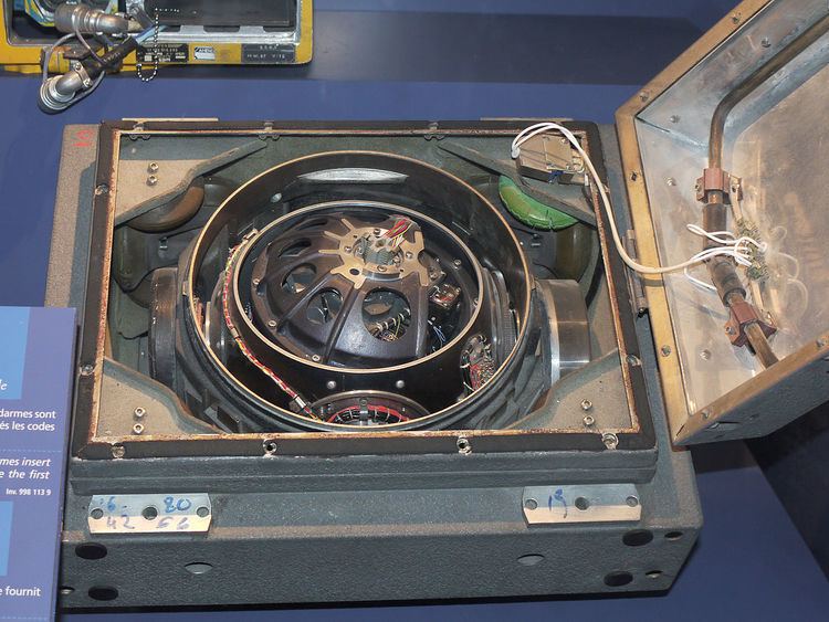
IMU assembly
High performance IMUs, or IMUs designed to operate under harsh conditions are very often suspended by shock absorbers. These shock absorbers are required to master three effects:
- reduce sensor errors due to mechanical environment solicitations
- protect sensors as they can be damaged by shocks or vibrations
- contain parasitic IMU movement within a limited bandwidth, where processing will be able to compensate for them.
Suspended IMUs can offer very high performance, even when submitted to harsh environments. However, to reach such performance, it is necessary to compensate for three main resulting behaviors:
- coning: is a parasitic effect induced by two orthogonal rotations
- sculling: is a parasitic effect induced by an acceleration orthogonal to a rotation
- centrifugal accelerations effects. Decreasing these errors tends to push IMU designers to increase processing frequencies, which becomes easier using recent digital technologies. However developing algorithms able to cancel these errors requires deep inertial knowledge and strong intimacy with sensors/IMU design. On the other side, if suspension is likely to enable IMU performance increase, it has a side effect on size and mass.