
 | ||
A gyroscope (from Ancient Greek γῦρος gûros, "circle" and σκοπέω skopéō, "to look") is a spinning wheel or disc in which the axis of rotation is free to assume any orientation by itself. When rotating, the orientation of this axis is unaffected by tilting or rotation of the mounting, according to the conservation of angular momentum. Because of this, gyroscopes are useful for measuring or maintaining orientation.
Contents
- Description and diagram
- History
- Steadicam
- Heading indicator
- Gyrocompass
- Accelerometer
- Gyrostat
- MEMS
- HRG
- VSG or CVG
- DTG
- Ring laser gyroscope
- Fiber optic gyroscope
- London moment
- Consumer electronics
- References
Gyroscopes based on other operating principles also exist, such as the electronic, microchip-packaged MEMS gyroscopes found in consumer electronics devices, solid-state ring lasers, fibre optic gyroscopes, and the extremely sensitive quantum gyroscope.
Applications of gyroscopes include inertial navigation systems where magnetic compasses would not work, as in the Hubble telescope, or inside the steel hull of a submerged submarine, or would not be precise enough. Due to their precision, gyroscopes are also used in gyrotheodolites to maintain direction in tunnel mining. Gyroscopes can be used to construct gyrocompasses, which complement or replace magnetic compasses (in ships, aircraft and spacecraft, vehicles in general), to assist in stability (Hubble Space Telescope, bicycles, motorcycles, and ships) or be used as part of an inertial guidance system. However, it should be mentioned that Dr. Robert E. Klein of the Mechanical Engineering Dept., University of Illinois at Urbana-Champaign, showed conclusively, by a sequence of experiments, that gyroscopic action is not needed for the stability of a bicycle.
Description and diagram
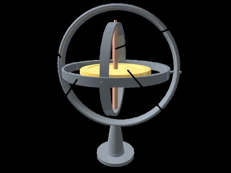
A gyroscope is a wheel mounted in two or three gimbals, which are a pivoted supports that allow the rotation of the wheel about a single axis. A set of three gimbals, one mounted on the other with orthogonal pivot axes, may be used to allow a wheel mounted on the innermost gimbal to have an orientation remaining independent of the orientation, in space, of its support. In the case of a gyroscope with two gimbals, the outer gimbal, which is the gyroscope frame, is mounted so as to pivot about an axis in its own plane determined by the support. This outer gimbal possesses one degree of rotational freedom and its axis possesses none. The inner gimbal is mounted in the gyroscope frame (outer gimbal) so as to pivot about an axis in its own plane that is always perpendicular to the pivotal axis of the gyroscope frame (outer gimbal). This inner gimbal has two degrees of rotational freedom.
The axle of the spinning wheel defines the spin axis. The rotor is constrained to spin about an axis, which is always perpendicular to the axis of the inner gimbal. So the rotor possesses three degrees of rotational freedom and its axis possesses two. The wheel responds to a force applied to the input axis by a reaction force to the output axis.
The behaviour of a gyroscope can be most easily appreciated by consideration of the front wheel of a bicycle. If the wheel is leaned away from the vertical so that the top of the wheel moves to the left, the forward rim of the wheel also turns to the left. In other words, rotation on one axis of the turning wheel produces rotation of the third axis.
A gyroscope flywheel will roll or resist about the output axis depending upon whether the output gimbals are of a free or fixed configuration. Examples of some free-output-gimbal devices would be the attitude reference gyroscopes used to sense or measure the pitch, roll and yaw attitude angles in a spacecraft or aircraft.
The centre of gravity of the rotor can be in a fixed position. The rotor simultaneously spins about one axis and is capable of oscillating about the two other axes, and, thus, except for its inherent resistance due to rotor spin, it is free to turn in any direction about the fixed point. Some gyroscopes have mechanical equivalents substituted for one or more of the elements. For example, the spinning rotor may be suspended in a fluid, instead of being pivotally mounted in gimbals. A control moment gyroscope (CMG) is an example of a fixed-output-gimbal device that is used on spacecraft to hold or maintain a desired attitude angle or pointing direction using the gyroscopic resistance force.
In some special cases, the outer gimbal (or its equivalent) may be omitted so that the rotor has only two degrees of freedom. In other cases, the centre of gravity of the rotor may be offset from the axis of oscillation, and, thus, the centre of gravity of the rotor and the centre of suspension of the rotor may not coincide.
History
Essentially, a gyroscope is a top combined with a pair of gimbals. Tops were invented in many different civilizations, including classical Greece, Rome, and China. Most of these were not utilized as instruments.
The first known apparatus similar to a gyroscope (the "Whirling Speculum" or "Serson's Speculum") was invented by John Serson in 1743. It was used as a level, to locate the horizon in foggy or misty conditions.
The first instrument used more like an actual gyroscope was made by German Johann Bohnenberger, who first wrote about it in 1817. At first he called it the "Machine". Bohnenberger's machine was based on a rotating massive sphere. In 1832, American Walter R. Johnson developed a similar device that was based on a rotating disc. The French mathematician Pierre-Simon Laplace, working at the École Polytechnique in Paris, recommended the machine for use as a teaching aid, and thus it came to the attention of Léon Foucault. In 1852, Foucault used it in an experiment involving the rotation of the Earth. It was Foucault who gave the device its modern name, in an experiment to see (Greek skopeein, to see) the Earth's rotation (Greek gyros, circle or rotation), which was visible in the 8 to 10 minutes before friction slowed the spinning rotor.
In the 1860s, the advent of electric motors made it possible for a gyroscope to spin indefinitely; this led to the first prototype heading indicators, and a rather more complicated device, the gyrocompass. The first functional gyrocompass was patented in 1904 by German inventor Hermann Anschütz-Kaempfe. The American Elmer Sperry followed with his own design later that year, and other nations soon realized the military importance of the invention—in an age in which naval prowess was the most significant measure of military power—and created their own gyroscope industries. The Sperry Gyroscope Company quickly expanded to provide aircraft and naval stabilizers as well, and other gyroscope developers followed suit.
In 1917, the Chandler Company of Indianapolis, created the "Chandler gyroscope", a toy gyroscope with a pull string and pedestal. Chandler continued to produce the toy until the company was purchased by TEDCO inc. in 1982. The chandler toy is still produced by TEDCO today.
In the first several decades of the 20th century, other inventors attempted (unsuccessfully) to use gyroscopes as the basis for early black box navigational systems by creating a stable platform from which accurate acceleration measurements could be performed (in order to bypass the need for star sightings to calculate position). Similar principles were later employed in the development of inertial navigation systems for ballistic missiles.
During World War II, the gyroscope became the prime component for aircraft and anti-aircraft gun sights. After the war, the race to miniaturize gyroscopes for guided missiles and weapons navigation systems resulted in the development and manufacturing of so-called midget gyroscopes that weighed less than 3 ounces (85 g) and had a diameter of approximately 1 inch (2.5 cm). Some of these miniaturized gyroscopes could reach a speed of 24,000 revolutions per minute in less than 10 seconds.
Gyroscopes continue to be an engineering challenge. For example, the axle bearings have to be extremely accurate. A small amount of friction is deliberately introduced to the bearings, since otherwise an accuracy of better than
Three-axis MEMS-based gyroscopes are also being used in portable electronic devices such as tablets, smartphones, and smartwatches. This adds to the 3-axis acceleration sensing ability available on previous generations of devices. Together these sensors provide 6 component motion sensing; acceleration for X,Y, and Z movement, and gyroscopes for measuring the extent and rate of rotation in space (roll, pitch and yaw). Some devices (e.g. the iPhone) additionally incorporate a magnetometer to provide absolute angular measurements relative to the Earth's magnetic field. Newer MEMS-based inertial measurement units incorporate up to all nine axes of sensing in a single integrated circuit package, providing inexpensive and widely available motion sensing.
Steadicam
A Steadicam rig was employed during the filming of Return of the Jedi, in conjunction with two gyroscopes for extra stabilization, to film the background plates for the speeder bike chase. Steadicam inventor Garrett Brown operated the shot, walking through a redwood forest, running the camera at one frame per second. When projected at 24 frames per second, it gave the impression of flying through the air at perilous speeds.
Heading indicator
The heading indicator or directional gyro has an axis of rotation that is set horizontally, pointing north. Unlike a magnetic compass, it doesn't seek north. When being used in an airliner, for example, it will slowly drift away from north, and will need to be reoriented periodically, using a magnetic compass as a reference.
Gyrocompass
Unlike a directional gyro or heading indicator, a gyrocompass seeks north. It detects the rotation of the Earth about its axis and seeks the true north, rather than the magnetic north. Gyrocompasses usually have inbuilt damping to prevent overshoot when recalibrating due to sudden movement.
Accelerometer
Another problem to be solved is to determine where one is. By determining one's acceleration and integrating over time, one can determine one's velocity. Integrating again, one can find one's position. The simplest accelerometer, conceptually, is a weight that is free to move horizontally, attached to a spring and a device to measure the tension in the spring. This can be improved by introducing a counteracting force to push the weight back and to measure the force needed to prevent the weight from moving. A more complicated design consists of a gyroscope with a weight on one of the axes. The device will react to the force generated by the weight when it is accelerated, by integrating that force to produce a velocity. Thus only one more integration is needed to obtain one's position.
Gyrostat
A gyrostat is a variant of the gyroscope. It consists of a massive flywheel concealed in a solid casing. Its behaviour on a table, or with various modes of suspension or support, serves to illustrate the curious reversal of the ordinary laws of static equilibrium due to the gyrostatic behaviour of the interior invisible flywheel when rotated rapidly. The first gyrostat was designed by Lord Kelvin to illustrate the more complicated state of motion of a spinning body when free to wander about on a horizontal plane, like a top spun on the pavement, or a hoop or bicycle on the road. Kelvin also made use of gyrostats to develop mechanical theories of the elasticity of matter and of the ether; these theories are of purely historical interest today.
In modern times, the gyrostat concept is used in the design of attitude control systems for orbiting spacecraft and satellites. For instance, the Mir space station had three pairs of internally mounted flywheels known as gyrodynes or control moment gyros.
In physics, there are several systems whose dynamical equations resemble the equations of motion of a gyrostat. Examples include a solid body with a cavity filled with an inviscid, incompressible, homogeneous liquid, the static equilibrium configuration of a stressed elastic rod in elastica theory, the polarization dynamics of a light pulse propagating through a nonlinear medium, the Lorenz system in chaos theory, and the motion of an ion in a Penning trap mass spectrometer.
MEMS
A MEMS gyroscope takes the idea of the Foucault pendulum and uses a vibrating element, known as a MEMS (microelectromechanical system). The MEMS-based gyro was initially made practical and producible by Systron Donner Inertial (SDI). Today, SDI is a large manufacturer of MEMS gyroscopes.
HRG
The hemispherical resonator gyroscope (HRG), also called wine-glass gyroscope or mushroom gyro, makes using a thin solid-state hemispherical shell, anchored by a thick stem. This shell is driven to a flexural resonance by electrostatic forces generated by electrodes which are deposited directly onto separate fused-quartz structures that surround the shell. Gyroscopic effect is obtained from the inertial property of the flexural standing waves.
VSG or CVG
A vibrating structure gyroscope (VSG), also called a Coriolis vibratory gyroscope (CVG), uses a resonator made of different metallic alloys. It takes a position between the low-accuracy, low-cost MEMS gyroscope and the higher-accuracy and higher-cost FOG. Accuracy parameters are increased by using low-intrinsic damping materials, resonator vacuumization, and digital electronics to reduce temperature dependent drift and instability of control signals.
High quality wine-glass resonators are used for precise sensors like HRG or CRG.
DTG
A dynamically tuned gyroscope (DTG) is a rotor suspended by a universal joint with flexure pivots. The flexure spring stiffness is independent of spin rate. However, the dynamic inertia (from the gyroscopic reaction effect) from the gimbal provides negative spring stiffness proportional to the square of the spin speed (Howe and Savet, 1964; Lawrence, 1998). Therefore, at a particular speed, called the tuning speed, the two moments cancel each other, freeing the rotor from torque, a necessary condition for an ideal gyroscope.
Ring laser gyroscope
A ring laser gyroscope relies on the Sagnac effect to measure rotation by measuring the shifting interference pattern of a beam split into two halves, as the two halves move around the ring in opposite directions.
When the Boeing 757-200 entered service in 1983, it was equipped with the first suitable ring laser gyroscope. This gyroscope took many years to develop, and the experimental models went through many changes before it was deemed ready for production by the engineers and managers of Honeywell and Boeing. It was an outcome of the competition with mechanical gyroscopes, which kept improving. The reason Honeywell, of all companies, chose to develop the laser gyro was that they were the only one that didn't have a successful line of mechanical gyroscopes, so they wouldn't be competing against themselves. The first problem they had to solve was that with laser gyros rotations below a certain minimum could not be detected at all, due to a problem called "lock-in", whereby the two beams act like coupled oscillators and pull each other's frequencies toward convergence and therefore zero output. The solution was to shake the gyro rapidly so that it never settled into lock-in. Paradoxically, too regular of a dithering motion produced an accumulation of short periods of lock-in when the device was at rest at the extremities of its shaking motion. This was cured by applying a random white noise to the vibration. The material of the block was also changed from quartz to a new glass ceramic Cer-Vit, made by Owens Corning, because of helium leaks.
Fiber optic gyroscope
A fiber optic gyroscope also uses the interference of light to detect mechanical rotation. The two halves of the split beam travel in opposite directions in a coil of fiber optic cable as long as 5 km. Like the ring laser gyroscope, it makes use of the Sagnac effect.
London moment
A London moment gyroscope relies on the quantum-mechanical phenomenon, whereby a spinning superconductor generates a magnetic field whose axis lines up exactly with the spin axis of the gyroscopic rotor. A magnetometer determines the orientation of the generated field, which is interpolated to determine the axis of rotation. Gyroscopes of this type can be extremely accurate and stable. For example, those used in the Gravity Probe B experiment measured changes in gyroscope spin axis orientation to better than 0.5 milliarcseconds (1.4×10⁻⁷ degrees) over a one-year period. This is equivalent to an angular separation the width of a human hair viewed from 32 kilometers (20 mi) away.
The GP-B gyro consists of a nearly-perfect spherical rotating mass made of fused quartz, which provides a dielectric support for a thin layer of niobium superconducting material. To eliminate friction found in conventional bearings, the rotor assembly is centered by the electric field from six electrodes. After the initial spin-up by a jet of helium which brings the rotor to 4,000 RPM, the polished gyroscope housing is evacuated to an ultra-high vacuum to further reduce drag on the rotor. Provided the suspension electronics remain powered, the extreme rotational symmetry, lack of friction, and low drag will allow the angular momentum of the rotor to keep it spinning for about 15,000 years.
A sensitive DC SQUID is able to discriminate changes as small as one quantum, or about 2 ×10⁻¹⁵ Wb, is used to monitor the gyroscope. A precession, or tilt, in the orientation of the rotor causes the London moment magnetic field to shift relative to the housing. The moving field passes through a superconducting pickup loop fixed to the housing, inducing a small electric current. The current produces a voltage across a shunt resistance, which is resolved to spherical coordinates by a microprocessor. The system is designed to minimize Lorentz torque on the rotor.
Consumer electronics
In addition to being used in compasses, aircraft, computer pointing devices, etc., gyroscopes have been introduced into consumer electronics. Since the gyroscope allows the calculation of orientation and rotation, designers have incorporated them into modern technology. The integration of the gyroscope has allowed for more accurate recognition of movement within a 3D space than the previous lone accelerometer within a number of smartphones. Gyroscopes in consumer electronics are frequently combined with accelerometers (acceleration sensors) for more robust direction- and motion-sensing. Examples of such applications include smartphones such as the Samsung Galaxy Note 4, HTC Titan, Nexus 5, iPhone 5s, Nokia 808 PureView and Sony Xperia, game console peripherals such as the PlayStation 3 controller and the Wii Remote, and virtual reality sets such as the Oculus Rift.
Nintendo has integrated a gyroscope into the Wii console's Wii Remote controller by an additional piece of hardware called "Wii MotionPlus". It is also included in the 3DS and the Wii U GamePad, which detects movement when turning.
Cruise ships use gyroscopes to level motion-sensitive devices such as self-leveling pool tables.
An electric powered flywheel gyroscope inserted in a bicycle wheel is being sold as a training wheel alternative.