
 | ||
An idler-wheel drive is a system used to transmit the rotation of the main shaft of a motor to another rotating device, for example the platter of a record-reproducing turntable or the crankshaft-to-camshaft gear train of an automobile.
Contents
Friction drive
An idler-wheel may be used as part of a friction drive mechanism, as in a phonograph, or as a belt tensioner in a belt drive system.
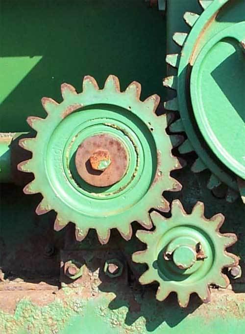
Idler gear
An idler gear is a gear wheel that is inserted between two or more other gear wheels. The purpose of an idler gear can be two-fold. Firstly, the idler gear will change the direction of rotation of the output shaft. Secondly, an idler gear can assist to reduce the size of the input/output gears whilst maintaining the spacing of the shafts.
Gear ratio
An idler gear does not affect the gear ratio between the input and output shafts. Note that in a sequence of gears chained together, the ratio depends only on the number of teeth on the first and last gear. The intermediate gears, regardless of their size, do not alter the overall gear ratio of the chain. But, of course, the addition of each intermediate gear reverses the direction of rotation of the final gear.
Likewise, the size of an idler wheel in a non-geared friction drive system does not affect the gear ratio between the input and output shafts. The surface speed of the input shaft is transferred directly to the surface speed of the idler wheel, and then from the idler wheel to the output shaft. A larger or smaller idler wheel maintains the same surface speed (which equals the surface speed of the input shaft), therefore the output shaft is driven at a constant speed regardless of the size of the idler wheel.
Applications
An intermediate gear which does not drive a shaft to perform any work is called an idler gear. Sometimes, a single idler gear is used to reverse the direction, in which case it may be referred to as a reverse idler. For instance, the typical automobile manual transmission engages reverse gear by means of inserting a reverse idler between two gears. Since a driven gear (gear "A") rotating clockwise will drive a second gear ("B") counterclockwise, adding a third gear to the string means that gear "C" will be spinning the same direction as "A". A typical transmission is designed with "A" and "B" gears, so when the engine spins, the outputs shaft spins the opposite direction, which drives the vehicle forward. A reverse idler gear setup is actually typically an "A" and a "C" gear, which are not in contact with each other until a "B" gear is moved between them. Since the transmission is designed to move the car forwards when the output is spinning in the opposite direction from the input shaft, when added to the "B" idler gear, it forces the "C" gear to spin in the same direction as the "A" gear, and thus the input and output shafts are spinning in the same direction, which drives the car in reverse.
Another scenario is a series of rollers, such as used for pressing paper. Each roller has to be powered, but adding a motor to each one is wasteful. One could simply add a gear onto the end of the shaft of each roller, but that means that each roller would be spinning the opposite direction of the one before. By simply adding a small idler gear between each larger gear, the result is a series of rollers, all being powered in the same direction.
Idler gears can also transmit rotation among distant shafts in situations where it would be impractical to simply make the distant gears larger to bring them together. Not only do larger gears occupy more space, but the mass and rotational inertia (moment of inertia) of a gear is quadratic in proportion to its radius. Instead of idler gears, of course, a toothed belt or a roller chain can be used to transmit torque over distance. For short distances, a train of idlers may be used; whether an odd or even number is used determines whether the final output gear rotates the same direction as the input gear or not. For longer distances, a roller chain or belt is quieter and creates less friction, although gears are typically stronger, depending and the strength of the roller chain. A case where numerous idler gears might be used is as described above, where there are a number of output gears that need to be driven simultaneously.
Caterpillar track idler wheels
A tracked vehicle uses a combination of wheels and rollers, including drive sprockets, idler wheels, track return rollers and road wheels. It is quite similar in concept to a conveyor belt, only instead of a machine carrying objects on top of a powered continuous belt, it's a machine that moves itself over a continuous belt. In a typical application, power is transmitted to a drive sprocket (or drive wheel), which drives the track around its loop. On the opposite end of the vehicle, there is an idler wheel, which provides a pulley wheel of sorts. On some applications, the drive sprocket and idler wheel carry some of the weight of the vehicle, for the purposes of this description, we will assume the drive sprocket and idler wheel are not weight-bearing units, and the drive sprocket is on the front (see M4 Sherman for an example). Since the drive sprocket can be at either the front (M4 Sherman) or the rear (M1 Abrahms) of the vehicle depending on the design, the idler wheel either carries the track back off the ground and returns it to the drive sprocket (rear idler wheel), or receives track from the drive sprocket and lays it down in front of the road wheels (front idler wheel). The idler wheel is not powered, just like an idler gear. Although it technically reverses the tracks direction (but not its rotation), this has nothing to do with the term "idler"; it is not related to an idler gear other than that they are both "idle", or not doing any work, only transmitting power ("idle" being a term for something or someone who isn't working). The road wheels are a series of non-powered wheels between the drive sprocket and idler wheel that serve to support the weight of the vehicle (and thus aren't considered "idle", even though they are unpowered). In higher speed applications, such as tanks and other AFV's, these road wheels are typically given some sort of suspension system to ease the ride, increase controllability, and decrease wear and tear. Due to the complications in adding suspension systems to the idler wheel and, in particular, the drive sprocket, in such vehicles, the road wheels typically carry all of the weight of the vehicle. In low speed applications, such as bulldozers, these road wheels lack any kind of suspension system, as the low speeds don't demand the cushioning. This also allows the idler and drive wheels to carry some of the weight, as their lack of suspension is made irrelevant. Track return rollers may or may not be used, and are simply small rollers which support the weight of the track as it's transferred from rear to front to be laid down again.The track simply provides a solid "road" for the road wheels to roll over on over all surfaces: the road wheels roll the vehicle along the self-created "road", while the drive sprocket forces the vehicle forward along the track and lays down "fresh" track. The idler picks the "used" track back up, and returns it back to the drive sprocket in the front. This is why an early term for a tracked vehicle was a "track-laying machine" (not to be confused with railroad track laying equipment). Transporting vehicles over muddy ground often required planks or logs to be placed along the track (see corduroy road, plank road). In the later 19th century, inventors figured out a way to make a rolling machine that would lay its own plank road wherever it went, negating the need for farmers to lay down logs in order to traverse muddy areas. Other benefits were discovered later.
Note that there are some non-powered tracked transports (i.e. trailers that roll on tracks rather than wheels), which have two idler wheels rather than a drive sprocket. There are also certain pieces of equipment, such as the Caterpillar D9 bulldozer, Tucker Sno-cat and Mattracks rubber track conversion kits, which configure their tracks in the shape of a triangle, or pyramid (when viewed from the side), with the drive sprocket at the tip of the pyramid. In this configuration, there are two idler/roadwheels and one drive sprocket (as well as a number of small, load-bearing roadwheels). In very rare cases, the vehicle lacks an idler wheel at all; in Northern regions, one way people got better traction in deep snow was to take a simple three-axle truck, and install a simple continuous track around the rear wheels, thus forming a basic half-track system which featured two drive wheels, and no idler or road wheels. One almost never sees this on true tracked vehicles, however, as the second drive wheel is redundant.