
 | ||
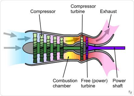
A free-turbine turboshaft is a form of turboshaft or turboprop gas turbine engine where the power is extracted from the exhaust stream of a gas turbine by a separate turbine, downstream of the gas turbine and is not connected to the gas turbine. This is opposed to the power being extracted from the power spool via a gear box.
Contents
The advantage of the free turbine is that the two turbines can operate at different speeds, and that these speeds can vary relative to each other. This is particularly advantageous for varying loads, such as turboprop engines.
Applications
Most turboshaft and turboprop engines now use free turbines. This includes those for static power generation, as marine propulsion and particularly for helicopters.
Helicopters
A major market for turboshaft engines is that for helicopters. When turboshaft engines became available in the 1950s, they were rapidly adopted for both new designs and as replacements for piston engines. They offered more power and far better power to weight ratios. Helicopters of this period had barely adequate performance; the switch to a turbine engine could both reduce several hundred pounds of engine weight, 600 lb (270 kg) for the Napier Gazelle of the Westland Wessex, and also allow considerably more payload weight. For the Westland Whirlwind, this converted the inadequate piston-engined HAS.7 to the de Havilland Gnome turbine-powered HAR.9. As one of the first anti-submarine helicopters, the HAS.7 had been so restricted for weight that it could carry either a search sonar or an attack torpedo, but not both.
The free-turbine engine was particularly favoured. It did not require a clutch, as the gas generator could be spun up to operating speed without requiring the output shaft to rotate. For the Wessex this was used to give a particularly fast take-off from a cold start. By locking the main rotor (and the power turbine) with the rotor brake, the engine could be spun up to operating speed, then lit, and when the engine core is at the operating speed of 10,500 rpm the brake is released and drive to the rotor smoothly increased as the power turbine gains speed. This was used to bring the rotor to speed from stationary in just 15 seconds and a time from engine start to take-off of only 30 seconds.
A further advantage of the free turbine design was the ease with which a counter-rotating engine could be designed and manufactured, simply by reversing the power turbine alone. This allowed handed engines to be made in pairs, when needed. It also allowed contra-rotating engines, where gas generator core and power turbine revolved in opposite directions, reducing the overall moment of inertia. For the helicopter engine replacement market, this ability allowed previous engines of either direction to be replaced simply. Some turboshaft engines' omni-angle freedom of their installation angle also allowed installation into existing helicopter designs, no matter how the previous engines had been arranged. In time though, the move towards axial LP compressors and so smaller diameter engines encouraged a move to the now standard layout of one or two engines set side-by-side, horizontally above the cabin.
Pusher propfans
An attractively simple configuration making use of the free turbine is the propfan engine, with a rear-mounted unducted fan in pusher configuration, rather than the more familiar tractor layout. The first such engine was the very early and promising Metropolitan-Vickers F.3 of 1942 with a ducted fan, followed by the unducted and much lighter F.5. Development of these engines stopped abruptly owing to corporate takeovers, rather than technical reasons. Rolls-Royce continued with design studies for such engines into the 1980s, as did GE, but they have yet to appear as commercial engines.
The advantage of the pusher propfan with a free power turbine is its simplicity. The prop blades are attached directly to the outside of the rotating turbine disc. No gearboxes or drive shafts are required. The short length of the rotating components also reduces vibration. The static structure of the engine over this length is a large diameter tube within the turbine. In most designs, two contra-rotating rings of turbine and propeller are used. Intermeshed contra-rotating turbines can act as the guide vanes for each other, removing the need for static vanes.
Risk of overspeed
A drawback to the simple free turbine turboprop is its behaviour if the load suddenly falls to zero. In such a case, the unconstrained free turbine overspeeds and will be destroyed by centrifugal forces.
Such a failure was the cause of the second prototype Bristol Britannia, G-ALRX's 1954 accident in the Severn Estuary. A failure in the propeller reduction gearbox led to an overspeed and destruction of the power turbine of Nº3 engine. In the confined space of the Britannia's Bristol Proteus engine, fragments perforated the oil tank and led to a fire, which threatened the integrity of the wing spar. The pilot, Bill Pegg, then made a forced landing on the estuary mud.
To avoid such accidents, free turbine engines, including the Proteus, are now commonly fitted with a device to shut off the fuel supply at the HP cock if torque in the turbine output shaft suddenly falls to zero.