
Wingspan 10 m Introduced August 1941 | Length 8.97 m Retired 1945 First flight June 1, 1939 | |
 | ||
Manufacturers Similar Messerschmitt Bf 109, Republic P 47 Thunderbolt, Curtiss P 40 Warhawk | ||
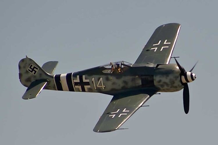
The Focke-Wulf Fw 190 Würger (English: Shrike) is a German single-seat, single-engine fighter aircraft designed by Kurt Tank in the late 1930s and widely used during World War II. Along with its well-known counterpart, the Messerschmitt Bf 109, the Fw 190 became the backbone of the Luftwaffe's Jagdwaffe (Fighter Force). The twin-row BMW 801 radial engine that powered most operational versions enabled the Fw 190 to lift larger loads than the Bf 109, allowing its use as a day fighter, fighter-bomber, ground-attack aircraft and, to a lesser degree, night fighter.
Contents
- Genesis
- Design concepts
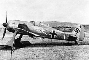
- First prototypes BMW 139
- Fw 190 A
- High altitude developments
- Ground attack versions BMW 801
- Trainer versions
- Fw 190 A 8R8 The Sturmbcke
- Combat history
- Production
- Surviving aircraft and modern replicas
- Operators
- Specifications Fw 190 A 8
- Specifications Fw 190 D 9
- References
The Fw 190A started flying operationally over France in August 1941, and quickly proved superior in all but turn radius to the Royal Air Force's main front-line fighter, the Spitfire Mk. V, especially at low and medium altitudes. The 190 maintained superiority over Allied fighters until the introduction of the improved Spitfire Mk. IX. In November/December 1942, the Fw 190 made its air combat debut on the Eastern Front, finding much success in fighter wings and specialised ground attack units called Schlachtgeschwader (Battle Wings or Strike Wings) from October 1943 onwards. In the opinion of German pilots who flew both the Bf 109 and the Fw 190, the latter provided increased firepower and, at low to medium altitude, manoeuvrability.
The Fw 190A series' performance decreased at high altitudes (usually 6,000 m (20,000 ft) and above), which reduced its effectiveness as a high-altitude interceptor. From the Fw 190's inception, there had been ongoing efforts to address this with a turbosupercharged BMW 801 in the B model, the much longer-nosed C model with efforts to also turbocharge its chosen Daimler-Benz DB 603 inverted V12 powerplant, and the similarly long-nosed D model with the Junkers Jumo 213. Problems with the turbocharger installations on the -B and -C subtypes meant only the D model would see service, entering service in September 1944. While these "long nose" versions gave them parity with Allied opponents, it arrived far too late in the war to have any real effect.
The Fw 190 was well-liked by its pilots. Some of the Luftwaffe's most successful fighter aces claimed a great many of their kills while flying it, including Otto Kittel, Walter Nowotny and Erich Rudorffer.
Genesis
Between 1934 and 1935 the German Ministry of Aviation (RLM) ran a contest to produce a modern fighter for the rearming Luftwaffe. Kurt Tank entered the parasol-winged Fw 159 into the contest, against the Arado Ar 80, Heinkel He 112 and Messerschmitt Bf 109. The Fw 159 was hopelessly outclassed, and was soon eliminated from the competition along with the Ar 80. The He 112 and Bf 109 were generally similar in design but the 109's lightweight construction gave it performance edge the 112 was never able to match. On 12 March 1936 the 109 was declared the winner.
Even before the 109 had entered squadron service, in autumn 1937 the RLM sent out a new tender asking various designers for a new fighter to fight alongside the Bf 109, as Walter Günther had done with his firm's follow-on to the unsuccessful He 112. Although the Bf 109 was an extremely competitive fighter, the Ministry was worried that future foreign designs might outclass it, and wanted to have new aircraft under development to meet these possible challenges. Kurt Tank responded with a number of designs, most based around a liquid-cooled inline engine.
However, it was not until a design was presented using the air-cooled, 14-cylinder BMW 139 radial engine that the Ministry of Aviation's interest was aroused. As this design used a radial engine, it would not compete with the inline-powered Bf 109 for engines, when there were already too few Daimler-Benz DB 601s to go around. This was not the case for competing designs like the Heinkel He 100 or twin-engined Focke-Wulf Fw 187, where production would compete with the 109 and Messerschmitt Bf 110 for engine supplies. After the war, Tank denied a rumour that he had to "fight a battle" with the Ministry to convince them of the radial engine's merits.
Design concepts
At the time, the use of radial engines in land-based fighters was relatively rare in Europe, as it was believed that their large frontal area would cause too much drag on something as small as a fighter. Tank was not convinced of this, having witnessed the successful use of radial engines by the U.S. Navy, and felt a properly streamlined installation would eliminate this problem.
The hottest points on any air-cooled engine are the cylinder heads, located around the circumference of a radial engine. In order to provide sufficient air to cool the engine, airflow had to be maximized at this outer edge. This was normally accomplished by leaving the majority of the front face of the engine open to the air, causing considerable drag. During the late 1920s, NACA led development of a dramatic improvement by placing an airfoil-shaped ring around the outside of the cylinder heads (the NACA cowling). The shaping accelerated the air as it entered the front of the cowl, increasing the total airflow, and allowing the opening in front of the engine to be made smaller.
Tank introduced a further refinement to this basic concept. He suggested placing most of the airflow components on the propeller, in the form of a oversized propeller spinner whose outside diameter was the same as the engine. The cowl around the engine proper was greatly simplified, essentially a basic cylinder. Air entered through a small hole at the centre of the spinner, and was directed through ductwork in the spinner so it was blowing rearward along the cylinder heads. To provide enough airflow, an internal cone was placed in the centre of the hole, over the propeller hub, which was intended to compress the airflow and allow a smaller opening to be used. In theory, the tight-fitting cowling also provided some thrust due to the compression and heating of air as it flowed through the cowling.
As to the rest of the design philosophy, Tank wanted something more than an aircraft built only for speed. Tank outlined the reasoning:
The Messerschmitt 109 [sic] and the British Spitfire, the two fastest fighters in world at the time we began work on the Fw 190, could both be summed up as a very large engine on the front of the smallest possible airframe; in each case armament had been added almost as an afterthought. These designs, both of which admittedly proved successful, could be likened to racehorses: given the right amount of pampering and easy course, they could outrun anything. But the moment the going became tough they were liable to falter. During World War I, I served in the cavalry and in the infantry. I had seen the harsh conditions under which military equipment had to work in wartime. I felt sure that a quite different breed of fighter would also have a place in any future conflict: one that could operate from ill-prepared front-line airfields; one that could be flown and maintained by men who had received only short training; and one that could absorb a reasonable amount of battle damage and still get back. This was the background thinking behind the Focke-Wulf 190; it was not to be a racehorse but a Dienstpferd, a cavalry horse.
In contrast to the complex, failure-prone fuselage mounted main gear legs of the earlier Fw 159, one of the main features of the Fw 190 was its wide-tracked, inwards-retracting landing gear. They were designed to withstand a sink rate of 4.5 meters per second (15 feet per second, 900 feet per minute), double the strength factor usually required. Hydraulic wheel brakes were used. The wide-track landing gear produced better ground handling characteristics, and the Fw 190 suffered fewer ground accidents than the Bf 109. (The Bf 109's narrow-track, outwards-retracting landing gear hinged on its wing root structure to help lower weight, but this led to inherent weakness and many failures and ground loops.) The Fw 190's retractable tail gear used a cable, anchored to the "elbow" at the midpoint of the starboard maingear's transverse retraction arms, which ran aftwards within the fuselage to the vertical fin to operate the tailwheel retraction function. The tailwheel's retraction mechanical design possessed a set of pulleys to guide the aforementioned cable to the top of the tailwheel's oleo strut, pulling it upwards along a diagonal track within the fin, into the lower fuselage — this mechanism was accessible through prominently visible twin triangular-shaped hinged panels, one per side, in the fin's side sheetmetal covering. On some versions of the Fw 190 an extended oleo strut could be fitted for larger-sized loads (such as bombs or even a torpedo) beneath the fuselage.
Most aircraft of the era used cables and pulleys to operate their controls. The cables tended to stretch, resulting in the sensations of "give" and "play" that made the controls less crisp and responsive, and required constant maintenance to correct. For the new design, the team replaced the cables with rigid pushrods and bearings to eliminate this problem. Another innovation was making the controls as light as possible. The maximum resistance of the ailerons was limited to 3.5 kg (8 lb), as the average man's wrist could not exert a greater force. The empennage (tail assembly) featured relatively small and well-balanced horizontal and vertical surfaces.
The design team also attempted to minimize changes in the aircraft's trim at varying speeds, thus reducing the pilot's workload. They were so successful in this regard that they found in-flight-adjustable aileron and rudder trim tabs were not necessary. Small, fixed tabs were fitted to control surfaces and adjusted for proper balance during initial test flights. Only the elevator trim needed to be adjusted in flight (a feature common to all aircraft). This was accomplished by tilting the entire horizontal tailplane with an electric motor, with an angle of incidence ranging from −3° to +5°.
Another aspect of the new design was the extensive use of electrically powered equipment instead of the hydraulic systems used by most aircraft manufacturers of the time. On the first two prototypes, the main landing gear was hydraulic. Starting with the third prototype, the undercarriage was operated by push buttons controlling electric motors in the wings, and was kept in position by electric up and down-locks. The armament was also loaded and fired electrically. Tank believed that service use would prove that electrically powered systems were more reliable and more rugged than hydraulics, electric lines being much less prone to damage from enemy fire.
Like the Bf 109, the Fw 190 featured a fairly small wing planform with relatively high wing loading. This presents a trade-off in performance. An aircraft with a smaller wing suffers less drag under most flight conditions and therefore flies faster and may have better range. However, it also means the wing generates less lift at lower speeds, making it less maneuverable and also reduces performance in the thinner air at higher altitudes. The wings spanned 9.5 m (31 ft 2 in) and had an area of 15 m² (161 ft²). The wing was designed using the NACA 23015.3 airfoil at the root and the NACA 23009 airfoil at the tip.
Earlier aircraft designs generally featured canopies consisting of small plates of perspex (called Plexiglas in the United States) in a metal framework, with the top of the canopy even with the rear fuselage. This design considerably limited visibility, especially to the rear. The introduction of vacuum forming led to the creation of the "bubble canopy" which was largely self-supporting, and could be mounted over the cockpit, offering greatly improved all-round visibility. Tank's design for the Fw 190 used a canopy with a frame that ran around the perimeter, with only a short, centerline seam along the top, running rearward from the radio antenna fitting where the three-panel windscreen and forward edge of the canopy met, just in front of the pilot.
The eventual choice of the BMW 801 14-cylinder radial over the more troublesome BMW 139 also brought with it a BMW-designed cowling "system" which integrated the radiator used to cool the motor oil. An annular, ring-shaped oil cooler core was built into the BMW-provided forward cowl, just behind the fan. The outer portion of the oil cooler's core was in contact with the main cowling's sheet metal. Comprising the BMW-designed forward cowl, in front of the oil cooler was a ring of metal with a C-shaped cross-section, with the outer lip lying just outside the rim of the cowl, and the inner side on the inside of the oil cooler core. Together, the metal ring and cowling formed an S-shaped duct with the oil cooler's core contained between them. Airflow past the gap between the cowl and outer lip of the metal ring produced a vacuum effect that pulled air from the front of the engine forward across the oil cooler core to provide cooling for the 801's motor oil. The rate of cooling airflow over the core could be controlled by moving the metal ring in order to open or close the gap. The reasons for this complex system were threefold. One was to reduce any extra aerodynamic drag of the oil radiator, in this case largely eliminating it by placing it within the same cowling as the engine. The second was to warm the air before it flowed to the radiator to aid warming the oil during starting. Finally, by placing the radiator behind the fan, cooling was provided even while the aircraft was parked. The disadvantage to this design was that the radiator was in an extremely vulnerable location, and the metal ring was increasingly armoured as the war progressed.
First prototypes (BMW 139)
Fw 190 A
A total of 13,291 Fw 190 A-model aircraft were produced.
High-altitude developments
Tank started looking at ways to address the altitude performance problem early in the program. In 1941, he proposed a number of versions featuring new powerplants, and he suggested using turbochargers in place of superchargers. Three such installations were outlined
Ground attack versions (BMW 801)
Trainer versions
Fw 190 A-8/R8 (The Sturmböcke)
The appearance of United States Army Air Forces heavy bombers caused a problem for the German fighter force. The B-17 Flying Fortress in particular could absorb heavy punishment. The armament of the Bf 109 and then current Fw 190 were not adequate for bomber-destroyer operations, with the B-17's eventual deployment in the combat box formations providing their defensive armament with formidable massed firepower from as many as one hundred Browning AN/M2 .50 caliber machine guns or more between all the bombers in such a formation, from almost any conceivable direction. In addition, the Luftwaffe's original solution of Zerstörer twin-engine Messerschmitt Bf 110G bomber destroyers, while effective against unescorted Allied bomber formations, lacked maneuverability and were eviscerated by the USAAF's fighter escorts in late 1943 and early 1944.
The Fw 190, designed as a rugged interceptor capable of withstanding considerable combat damage and delivering a potent 'punch' from its stable gun platform, was considered ideal for anti-bomber operations. Focke-Wulf redesigned parts of the wing structure to accommodate larger armament. The Fw 190A-6 was the first sub-variant to undergo this change. Its standard armament was increased from four MG 151/20s to two of them with four more in two underwing cannon pods. The aircraft was designated A-6/R1 (Rüstsatz; or field conversion model). The first aircraft were delivered on 20 November 1943. Brief trials saw the twin cannon replaced by the MK 108 30mm autocannon in the outer wing, which then became the A-6/R2. The cannons were blowback-operated, had electric ignition, and were belt fed. The 30mm MK 108 was simple to make and its construction was economical; the majority of its components consisted of just pressed sheet metal stampings. In the A-6/R4, the GM-1 (nitrous oxide) Boost was added for the BMW 801 engine to increase performance at high altitude. For protection, 30 millimetres (1.2 in) of armoured glass was added to the canopy. The A-6/R6 was fitted with twin heavy calibre Werfer-Granate 21 (BR 21) unguided, air-to-air rockets, fired from single underwing tubular launchers (one per wing panel). The increased modifications, in particular heavy firepower, made the Fw 190 a potent bomber-killer. The A-7 evolved in November 1943. Two synchronized 13mm (.51 caliber) MG 131 machine guns replaced the twin cowl-mount synchronized 7.92mm (.318 cal) MG 17 machine guns. The A-7/R variants could carry two 30mm MK 108s as well as BR 21 rockets. This increased its potency as a Pulk-Zerstörer (Bomber Formation Destroyer). The A-8/R2 was the most numerous Sturmbock aircraft, some 900 were built by Fiesler at Kassel with 30mm MK 108s installed in their outer wing panel mounts. While formidable bomber-killers, the armour and substantial up-gunning with heavier calibre firepower meant the Fw 190 was now cumbersome to maneuver. Vulnerable to Allied fighters, they had to be escorted by Bf 109s.
Two of the former Wilde Sau single-engined night fighter wings were reconstituted for their use, such as Jagdgeschwader 300 (JG 300, or Fighter Wing 300) and JG 301. These units consisted of Sturmböcke. However, JG 3 also had a special gruppe (group) of Sturmböcke. Willy Unger of 11.(Sturm)/JG 3 (11 Staffel (Squadron) of Sturmgruppe (Storm group) JG 3) made the following comments:
Advantages; wide undercarriage, large twin-row radial engine which protected the pilot from the front, electric starter motor and electric trim system. Disadvantages; there was a danger of turning over when braking hard on soft or sandy ground. In combat against enemy fighters, more awkward because of the heavy armour plating. Strong at low altitude, inferior to the Bf 109 at higher altitude. In my opinion the Fw 190, in this version, was the best aircraft used in the formation against the Viermots.
Richard Franz commented:
When we made our attack, we approached from slightly above, then dived, opening fire with 13mm and 20mm guns to knock out the rear gunner and then, at about 150 metres, we tried to engage with the MK 108 30mm cannon, which was a formidable weapon. It could cut the wing off a B-17. Actually, it was still easier to kill a B-24, which was somewhat weaker in respect of fuselage strength and armament. I think we generally had the better armament and ammunition, whereas they had the better aircraft.
Combat history
The Fw 190 participated on every major combat front where the Luftwaffe operated after 1941, and did so with success in a variety of roles.
Luftwaffe pilots who flew both the Fw 190 and the Bf 109 generally felt that, with the exception of high altitude capability, the Fw 190 was superior.
Production
A 0.40 km² (100 acre) Focke-Wulf plant east of Marienburg was bombed by the Eighth Air Force on 9 October 1944. In addition, one of the most important sub-contractors for the radial-engined Fw 190s was AGO Flugzeugwerke, which from 1941 through to the end of the war produced enough Fw 190s to earn it major attention from the USAAF, with the AGO plant in Oschersleben being attacked at least five times during the war from 1943 onwards.
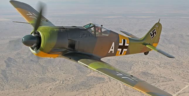
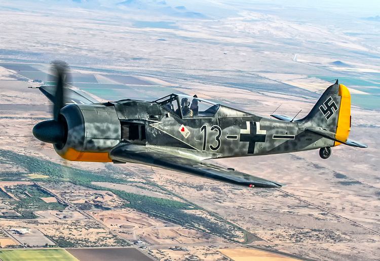
Surviving aircraft and modern replicas
Some 28 original Fw 190s are in museums or in the hands of private collectors around the world.
In 1997, a German company, Flug Werk GmbH, began manufacturing new Fw 190 models as reproductions. By 2012 almost 20 had been produced, most flyable, a few as static display models, with airworthy examples usually powered by Chinese-manufactured Shvetsov ASh-82 twin-row, 14-cylinder radial powerplants, which have a displacement of 41.2 litres, close to the BMW 801's 41.8 litres, with the same engine cylinder arrangement and number of cylinders.
The nearly intact wreck of an Fw 190 A-5 / U3 (Werknummer 151 227) that had crashed in a marsh in a forest near Saint Petersburg, Russia in 1943 was located in 1989. After restoration in the US, the Fw 190 flew again (with the original BMW 801 powerplant) on 1 December 2010. Following the successful test flight, the aircraft was then trucked up to the Flying Heritage Collection, where it was reassembled in April 2011 and returned to airworthy condition.
At least five surviving Fw 190A radial-engined aircraft are known to have been assigned to the Luftwaffe's JG 5 wing in Herdla, Norway. More German fighter aircraft on display in museums in the 21st century have originated from this unit than from any other Axis Powers' military aviation unit of World War II.
The Turkish Air Force retired all of its Fw 190A-3 fleet at the end of 1947 mostly because of lack of spare parts and biliteral agreements which requires retiring and scrapping of all German origin aircraft. Nonetheless all of retired Fw 190s were saved from scrapping. The aircraft are wrapped with protective clothes and preserved under the soil near Aviation Supply and Maintenance Center at Kayseri city. Several attempts have been made to move these aircraft to museums, none of them have been successful until 14 October 2016 when 50 of those 72 warplanes were discovered buried near Kayseri's abandoned airport.
Operators
Specifications (Fw 190 A-8)
Data from Fw 190 A8
General characteristics
Performance
Armament
Specifications (Fw 190 D-9)
Data from
General characteristics
Performance
Armament