
 | ||
History of the flying wing with larry rinek
A flying wing is a tailless fixed-wing aircraft that has no definite fuselage. The crew, payload, fuel, and equipment are typically housed inside the main wing structure, although a flying wing may have various small protuberances such as pods, nacelles, blisters, booms, or vertical stabilizers.
Contents
- History of the flying wing with larry rinek
- Northrop s yb 49 flying wing definitely wasn t a ufo
- History
- Design
- Engineering design
- Directional stability
- Yaw control
- Bi directional flying wing
- Related designs
- References
Similar aircraft designs that are not - strictly speaking - flying wings, are sometimes referred to as such. These types include blended wing body aircraft, and microlights (such as the Aériane Swift), which typically carry the pilot (and engine when fitted) below the wing.
Northrop s yb 49 flying wing definitely wasn t a ufo
History
Tailless aircraft have been experimented with since the earliest attempts to fly. From 1910 John William Dunne's swept-wing biplane and monoplane designs displayed inherent stability.
Hugo Junkers patented a wing-only air transport concept around the same time, in 1910. He saw it as a natural solution to the problem of building an airliner large enough to carry a reasonable passenger load and enough fuel to cross the Atlantic in regular service. He believed that the flying wing's potentially large internal volume and low drag made it an obvious design for this role. His deep-chord monoplane wing was incorporated in the otherwise conventional Junkers J 1 in December 1915. In 1919 he started work on his "Giant" JG1 design, intended to seat passengers within a thick wing, but two years later the Allied Aeronautical Commission of Control ordered the incomplete JG1 destroyed for exceeding postwar size limits on German aircraft. Junkers conceived futuristic flying wings for up to 1,000 passengers; the nearest this came to realization was in the 1931 Junkers G.38 34-seater Grossflugzeug airliner, which featured a large thick-chord wing providing space for fuel, engines, and two passenger cabins. However, it still required a short fuselage to house the crew and additional passengers.
The flying wing configuration was studied extensively from the 1920s, often in conjunction with other tailless designs.
The Soviet Boris Ivanovich Cheranovsky began testing tailless flying wing gliders in 1924 gliders, eventually producing the powered BICh-3.
After the 1920s, Soviet designers such as Boris Ivanovich Cheranovsky worked independently and in secret under Stalin. With significant breakthrough in materials and construction methods, aircraft such as the BICh-3, BICh-14, BICh-7A became possible. Men like Chizhevskij and Antonov also came into the spotlight of the Communist Party by designing aircraft like the tailless BOK-5 (Chizhevskij) and OKA-33 (the first ever built by Antonov) which were designated as "motorized gliders" due to their similarity to popular gliders of the time. The BICh-11 by Cheranovsky in 1932 was competing with the Horten brothers H1 and Adolf Galland at the Ninth Glider Competitions in 1933, but did not demonstrate in the 1936 summer Olympics in Berlin. The BICh-26 was one of the first attempts at a supersonic jet flying wing aircraft, ahead of its time in 1948. The airplane was not accepted by the military and the design died with Cheranovsky.
In Germany, Alexander Lippisch worked first on tailless types before progressively moving to flying wings, while the Horten brothers developed a series of flying wing gliders through the 1930s. The H1 glider was flown with partial success in 1933, and the subsequent H2 flown successfully in both glider and powered variants.
In the United States, from the 1930s Jack Northrop and Cheston L. Eshelman each worked on their own designs. The Northrop N-1M scale prototype for a long-range bomber flew in 1940.
Other 1930s examples of true flying wings include Frenchman Charles Fauvel's AV3 glider of 1933 and the American Freel Flying Wing glider flown in 1937. featuring a self-stabilizing airfoil on a straight wing.
By World War II aerodynamic issues were well enough understood for work on production prototypes to begin while research continued. In 1942 Northrop flew the N-9M scale development aircraft for a proposed long-range bomber. The German Horten Ho 229 of March 1944 was the world's first twin jet engine pure flying wing, and pre-production examples were test-flown during the closing stages of the war. The British Armstrong Whitworth A.W.52G of 1944 was a glider test bed for tailless resrearch. for the later Armstrong Whitworth A.W.52 jet-powered version.
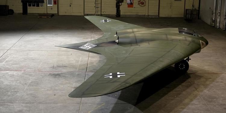
Several late-war German military designs were based on the flying wing concept (or variations of it) as a proposed solution to extend the range of the otherwise very short-range jet engine powered aircraft. Most famous example of these designs would be the Horten Ho 229 fighter-bomber, which first flew in 1944. It combined a flying wing, or Nurflügel, design with twin jet engines in its second, or "V2" (V for Versuch) prototype airframe flown by Erwin Ziller. However, a flameout in one of its Junkers Jumo 004 jet engines caused Ziller to crash, killing him. The unflown, nearly completed surviving "V3," or third prototype remains in storage at the Smithsonian Institution in an unrestored state.
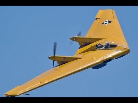
Some work continued postwar. The work on the Northrop N-1M led to the YB-35 long-range bomber, with pre-production machines flying in 1946. This was superseded the next year by conversion of the type to jet power as the YB-49 of 1947. The design did not necessarily offer a great advantage in range and presented a number of technical problems did not enter production.
Elsewhere, Turkey had been conducting research and the THK-13 appeared in 1948. Early proposals for the British Avro Vulcan by Roy Chadwick also explored flying wing designs.
With the arrival of the supersonic era, military interest faded due to the conflicting demands of a thin wing for supersonic flight against a thick wing to accommodate the crew and equipment.
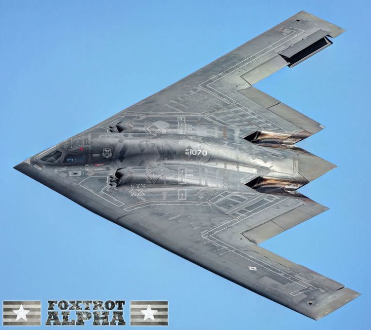
Interest in flying wings was renewed in the 1980s due to their potentially low radar reflection cross-sections. Stealth technology relies on shapes that reflect only radar waves in certain directions, thus making the aircraft hard to detect unless the radar receiver is at a specific position relative to the aircraft—a position that changes continuously as the aircraft moves. This approach eventually led to the Northrop Grumman B-2 Spirit stealth bomber. In this case, the aerodynamic advantages of the flying wing are not the primary reasons for the design's adoption. However, modern computer-controlled fly-by-wire systems allow for many of the aerodynamic drawbacks of the flying wing to be minimized, making for an efficient and effectively stable long-range bomber.
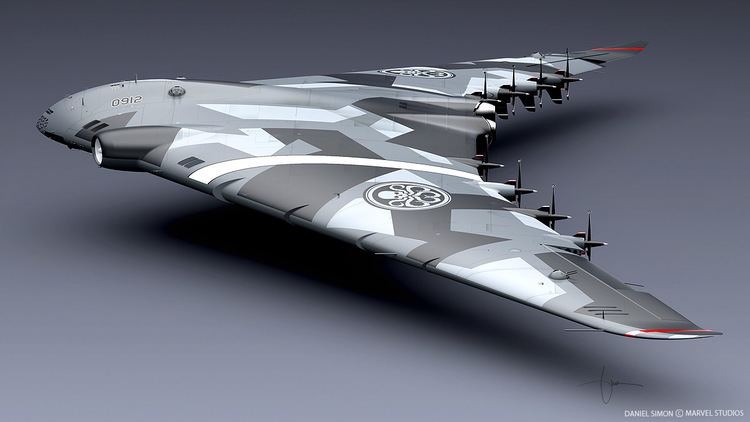
Due to the practical need for a deep wing, the flying wing concept is most practical for designs in the slow-to-medium speed range, and there has been continual interest in using it as a tactical airlifter design. Boeing continues to work on paper projects for a blended wing body, C-130 Hercules-size transport with better range and about one third more load, while maintaining the same size characteristics. A number of companies, including Boeing, McDonnell Douglas, and de Havilland, did considerable design work on flying wing airliners, but to date none has entered production.
Design
A clean flying wing is sometimes presented as theoretically the most aerodynamically efficient (lowest drag) design configuration for a fixed wing aircraft. It also would offer high structural efficiency for a given wing depth, leading to light weight and high fuel efficiency.
Because it lacks conventional stabilizing surfaces and the associated control surfaces, in its purest form the flying wing suffers from the inherent disadvantages of being unstable and difficult to control. These compromises are difficult to reconcile, and efforts to do so can reduce or even negate the expected advantages of the flying wing design, such as reductions in weight and drag. Moreover, solutions may produce a final design that is still too unsafe for certain uses, such as commercial aviation.
Further difficulties arise from the problem of fitting the pilot, engines, flight equipment, and payload all within the depth of the wing section.
Other known problems with the flying wing design relate to pitch and yaw. Pitch issues are discussed in the article on tailless aircraft. The problems of yaw are discussed below.
Engineering design
A wing that is made deep enough to contain the pilot, engines, fuel, undercarriage and other necessary equipment will have an increased frontal area, when compared with a conventional wing and long-thin fuselage. This can actually result in higher drag and thus lower efficiency than a conventional design. Typically the solution adopted in this case is to keep the wing reasonably thin, and the aircraft is then fitted with an assortment of blisters, pods, nacelles, fins, and so forth to accommodate all the needs of a practical aircraft.
The problem becomes more acute at supersonic speeds, where the drag of a thick wing rises sharply and it is essential for the wing to be made thin. No supersonic flying wing has ever been built.
Directional stability
For any aircraft to fly without constant correction it must have directional stability in yaw.
Flying wings lack anywhere to attach an efficient vertical stabilizer or fin. Any fin must attach directly on to the rear part of the wing, giving a small moment arm from the aerodynamic center, which in turn means that the fin is inefficient and to be effective the fin area must be large. Such a large fin has weight and drag penalties, and can negate the advantages of the flying wing. The problem can be minimized by increasing the wing sweepback and placing twin fins outboard near the tips, as for example in a low-aspect-ratio delta wing, but many flying wings have gentler sweepback and consequently have, at best, marginal stability.
Another solution is to angle or crank the wing tip sections downward with significant anhedral, increasing the area at the rear of the aircraft when viewed from the side.
The frontal area of a swept wing as seen in the direction of the airflow depends on the yaw angle relative to the airflow. Yaw increases the drag of the leading wing and reduces that of the trailing one. With enough sweep-back, differential drag is sufficient to naturally re-align the aircraft. This is the stabilization scheme used in the early Northrop flying wings, in combination with vertical engine nacelles (YB-35) or diminutive stabilizers (YB-49).
A complementary approach uses differential twist or wash out, together with a swept-back wing planform and a suitable airfoil section. Prandtl, Pankonin and others discovered that washout was fundamental to the yaw stability in a turn of the Horten brothers flying wings of the 1930s and 1940s. Due to the necessity for elevons to be located near the wingtips, the one on the upward-moving wing causes drag that impedes turning as it deflects the high-pressure airflow under the wing. The Hortens described a "bell shaped lift distribution" across the span of the wing, with more lift in the center section and less at the tips due to their reduced angle of incidence, or washing out. The restoration of outer lift by the elevon creates a slight thrust for the rear (outer) section of the wing during the turn. When displaced, this vector essentially pulls the trailing wing forward to compensate for the "adverse yaw" caused by the elevon. It did not work well in practice.
Yaw control
In some flying wing designs, any stabilizing fins and associated control rudders would be too far forward to have much effect, thus alternative means for yaw control are sometimes provided.
One solution to the control problem is differential drag: the drag near one wing tip is artificially increased, causing the aircraft to yaw in the direction of that wing. Typical methods include:
A consequence of the differential drag method is that if the aircraft maneuvers frequently then it will frequently create drag. So flying wings are at their best when cruising in still air: in turbulent air or when changing course, the aircraft may be less efficient than a conventional design.
Bi-directional flying wing
The supersonic bi-directional flying wing design comprises a long-span low speed wing and a short-span high speed wing joined in the form of an unequal cross.
The proposed craft would take off and land with the low-speed wing across the airflow, then rotate a quarter-turn so that the high-speed wing faces the airflow for supersonic travel. NASA has funded a study of the proposal.
The design is claimed to feature low wave drag, high subsonic efficiency and little or no sonic boom.
The proposed low-speed wing would have a thick, rounded airfoil able to contain the payload and a long span for high efficiency, while the high-speed wing would have a thin, sharp-edged airfoil and a shorter span for low drag at supersonic speed.
Related designs
Some related aircraft that are not strictly flying wings have been described as such.
Some types, such as the Northrop Flying Wing (NX-216H), still have a tail stabilizer mounted on tail booms, although they lack a fuselage.
Many hang gliders and microlight aircraft are tailless. Although sometimes referred to as flying wings, these types carry the pilot (and engine where fitted) below the wing structure rather than inside it, and so are not true flying wings.
An aircraft of sharply swept delta planform and deep center section represents a borderline case between flying wing, blended wing body, and/or lifting body configurations.