
Also called E-Engine and F-Engine | Cylinder bore 9 ⁄16 in (230 mm) | |
 | ||
Production 1965–1983; limited runs through the 1990s Displacement 5,160 to 12,900 cu in(84.6 to 211.4 L)645 cu in (10.6 L) per cylinder | ||
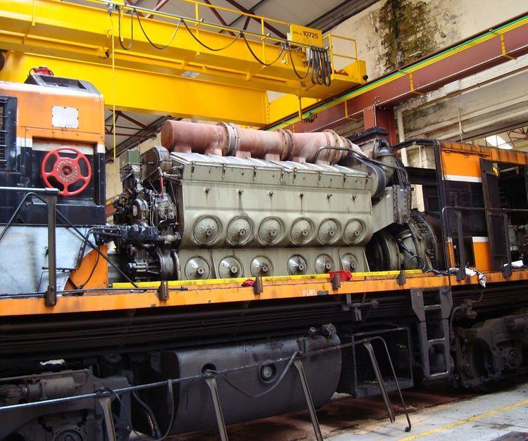
The EMD 645 family of diesel engines was designed and manufactured by the Electro-Motive Division of General Motors. While the 645 series was intended primarily for locomotive, marine and stationary engine use, one 16-cylinder version powered the 33-19 "Titan" prototype haul truck designed by GM's Terex division.
Contents
The 645 series was an evolution of the earlier 567 series and a precursor to the later 710 series. First introduced in 1965, the EMD 645 series remained in production on a by-request basis long after it was replaced by the 710, and most 645 service parts are still in production. The EMD 645 engine series is currently supported by Electro-Motive Diesel, Inc., which purchased the assets of the Electro-Motive Division from General Motors in 2005.
In 1951, E. W. Kettering wrote a paper for the ASME entitled, History and Development of the 567 Series General Motors Locomotive Engine, which goes into great detail about the technical obstacles that were encountered during the development of the 567 engine. These same considerations apply to the 645 and 710, as these engines were a logical extension of the 567C, by applying a cylinder bore increase, 645, and a cylinder bore increase and a stroke increase, 710, to achieve a greater power output, without changing the external size of the engines, or their weight, thereby achieving significant improvements in horsepower per unit volume and horsepower per unit weight.
History
The 645 series engines entered production in 1965. As the 567 series had reached its limits in horsepower increases, a larger displacement was needed; this was accomplished by increasing the bore from 8 1⁄2 in (216 mm) on the 567 series to 9 1⁄16 in (230 mm) on the 645 series, while maintaining the same stroke and deck height. While the crankcase was modified from the 567 series, 567C and later engines (or 567 engines which have been modified to 567C specifications, sometimes referred to as 567AC or 567BC engines) can accept 645 series service parts, such as power assemblies. Conversely, the 567E engine employs a 645E series block with 567 series power assemblies.
All 645 engines utilize either a Roots blower or a turbocharger for cylinder scavenging. The turbocharger (a combination turbo-compressor system) follows EMD's innovative design that uses a gear train and over-running clutch to drive the compressor rotor during low engine speed, when exhaust gas temperature (and, correspondingly, heat energy) alone is insufficient to drive the turbine. At higher engine speeds, increased exhaust gas temperature is sufficient to drive the turbine and the clutch disengages, turning the turbo-compressor system into a true turbocharger. The turbo-compressor can revert to compressor mode momentarily during demands for large increases in engine output power. While more expensive to maintain than Roots blowers, the turbocharger significantly reduces fuel consumption and emissions, while improving high-altitude performance. Additionally, EMD's turbo-compressor can provide a 50 percent increase in maximum rated horsepower over Roots-blown engines for the same engine displacement (2,000 hp or 1,500 kW for the Roots-blown 16-645, and 3,000 hp or 2,200 kW for the turbocharged 16-645, and similar increases for 12- and 8-cylinder 645s).
Horsepower for naturally aspirated engines (including Roots-blown two-stroke engines) is usually derated 2.5 percent per 1,000 feet (300 m) above mean sea level, a tremendous penalty at the 10,000 feet (3,000 m) or greater elevations which several Western U.S. and Canada railroads operate, and this can amount to a 25 percent power loss. Turbocharging effectively eliminates this derating.
The 645 series has a maximum engine speed of between 900 and 950 revolutions per minute (rpm), an increase over the 800 to 900 rpm maximum speed for the 567 series. An engine speed of 900 rpm was essential for 60 Hz stationary power generator applications and certain passenger locomotives equipped with 60 Hz, 480-volt three-phase "head-end power" systems. When used solely for traction purposes, the engine speed varies depending on the throttle position. The 950 rpm maximum speed of the 645F engine proved to be too high, thereby compromising its reliability, and the replacement engine, the 710G, reverted to 900 rpm maximum speed.
EMD built an SD40 demonstrator (number 434) in July 1964 to field test the 16-645E3 engine, followed by another eight SD40 demonstrators (numbers 434A through 434H) and a GP40 demonstrator (number 433A) in 1965. In December 1965 and January 1966, EMD built three SD45 demonstrators (numbers 4351 through 4353) to field test the 20-645E3 engine.
When the 645 engine entered production in 1965, a large series of new locomotive models was introduced. The turbocharged version was used in EMD's 40 Series (GP40, SD40 and SD45) in 3,000 horsepower (2,200 kW), sixteen-cylinder form and in 3,600 horsepower (2,700 kW), twenty-cylinder form. EMD also introduced the Roots-blown 38 Series (GP38, SD38) and turbocharged, twelve-cylinder 39 Series (GP39, SD39). All of these locomotive models extensively share common components and subsystems, thereby significantly reducing cost and increasing interchangeability. The GP38-2 and SD40-2 became the most popular models of the series and among the most popular locomotive models ever built.
Starting with the introduction of the 645 series engines, EMD's model naming convention generally increased model designs by ten (such as with the 40, 50, 60 and 70 series). The number was reduced by one for twelve-cylinder versions (such as the 39, 49 and 59 series); reduced by two for Roots-blown versions (for the 38 series); and increased by five for higher-horsepower versions (such as the 45 and 75 series).
Unlike the 645 series, the 710 series does not offer a Roots-blown model, but nothing in the basic design of that engine prevents such an offering, although a pair of Roots blowers which would be required for a Roots-blown 710 series likely would be too large (too long) to fit in the available carbody space, and making a special carbody just for the very few likely to be ordered would be economically unsound.
Specifications (many are common to 567 and 710 engines)
All 645 engines are two-stroke 45-degree V-engines. Each cylinder is of 645 cubic inches (10.57 L) displacement, hence the name; with a bore of 9 1⁄16 inches (230 mm), a stroke of 10 inches (254 mm) and a compression ratio of 14.5:1. The engine is a uniflow design with four poppet-type exhaust valves in the cylinder head and charge air scavenging ports within the sides of the cylinders. All engines use a single overhead camshaft per bank, with exhaust valves operated by two cam lobes (each of which operates two exhaust valves through a "bridge") and one cam lobe to operate the Unit injector which is in the center of the four exhaust valves. Rocker arms are roller-equipped to eliminate friction while hydraulic valve actuators are used to eliminate valve lash. Post-1995 710 engines employ Electronic Unit injectors, however these injectors still utilize a camshaft-actuated piston pump, as on non-EFI injectors.
Cylinders in each V-pair are directly opposite each other, and since all rods are always in compression, the connecting rods use a simple system of "fork" rods on one bank of cylinders and "blade" rods on the other (with the same stroke on both banks). As all rods are alternately in compression or tension throughout all four engine cycles, competitor General Electric in its 7FDL engine series uses the more complex "articulated" connecting rods (with a slightly longer stroke on the bank with articulated rods). The engines are provided with either a single or twin Roots blower, or a single mechanically-assisted turbocharger, depending on required power output.
For maintenance, a power assembly, consisting of a cylinder head, cylinder liner, piston, piston carrier and piston rod can be individually replaced relatively easily and quickly. The engine block is made from flat, formed and rolled structural steel members and steel forgings welded into a single structure (a "weldment"), so it can easily be repaired using conventional shop tools.
Stationary/marine versions
Like most EMD engines, the 645 is also sold for stationary and marine applications.
Stationary and marine installations are available with either a left or right-hand rotating engine.
Marine engines differ from railroad and stationary engines mainly in the shape and depth of the engine's oil sump, which has been altered to accommodate the rolling and pitching motions encountered in marine applications.
Engine Speed
Brake Horsepower (ABS Rating)