
 | ||
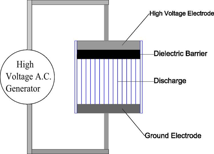
Dielectric-barrier discharge (DBD) is the electrical discharge between two electrodes separated by an insulating dielectric barrier. Originally called silent (inaudible) discharge and also known as ozone production discharge or partial discharge, it was first reported by Ernst Werner von Siemens in 1857. On right, the schematic diagram shows a typical construction of a DBD wherein one of the two electrodes is covered with a dielectric barrier material. The lines between the dielectric and the electrode are representative of the discharge filaments, which are normally visible to the naked eye. Below this, the photograph shows an atmospheric DBD discharge occurring in between two steel electrode plates, each covered with a dielectric (mica) sheet. The filaments are columns of conducting plasma, and the foot of each filament is representative of the surface accumulated charge.
Contents
Process
The process normally uses high voltage alternating current, ranging from lower RF to microwave frequencies. However, other methods were developed to extend the frequency range all the way down to the DC. One method was to use a high resistivity layer to cover one of the electrodes. This is known as the resistive barrier discharge. Another technique using a semiconductor layer of gallium arsenide (GaAs) to replace the dielectric layer, enables these devices to be driven by a DC voltage between 580 V and 740 V.
Construction
DBD devices can be made in many configurations, typically planar, using parallel plates separated by a dielectric or cylindrical, using coaxial plates with a dielectric tube between them. In a common coaxial configuration, the dielectric is shaped in the same form as common fluorescent tubing. It is filled at atmospheric pressure with either a rare gas or rare gas-halide mix, with the glass walls acting as the dielectric barrier. Due to the atmospheric pressure level, such processes require high energy levels to sustain. Common dielectric materials include glass, quartz, ceramics and polymers. The gap distance between electrodes varies considerably, from less than 0.1 mm in plasma displays, several millimetres in ozone generators and up to several centimetres in CO2 lasers.
Depending on the geometry, DBD can be generated in a volume (VDBD) or on a surface (SDBD). For VDBD the plasma is generated between two electrodes, for example between two parallel plates with a dielectric in between. At SDBD the microdischarges are generated on the surface of a dielectric, which results in a more homogeneous plasma than can be achieved using the VDBD configuration At SDBD the microdischarges are limited to the surface, therefore their density is higher compared to the VDBD. The plasma is generated on top of the surface of an SDBD plate.
A particular compact and economic DBD plasma generator can be built based on the principles of the piezoelectric direct discharge. In this technique, the high voltage is generated with a piezo-transformer, the secondary circuit of which acts also as the high voltage electrode. Since the transformer material is a dielectric, the produced electric discharge resembles properties of the dielectric barrier discharge.
Operation
A multitude of random arcs form in operation gap exceeding 1.5 mm between the two electrodes during discharges in gases at the atmospheric pressure . As the charges collect on the surface of the dielectric, they discharge in microseconds (millionths of a second), leading to their reformation elsewhere on the surface. Similar to other electrical discharge methods, the contained plasma is sustained if the continuous energy source provides the required degree of ionization, overcoming the recombination process leading to the extinction of the discharge plasma. Such recombinations are directly proportional to the collisions between the molecules and in turn to the pressure of the gas, as explained by Paschen's Law. The discharge process causes the emission of an energetic photon, the frequency and energy of which corresponds to the type of gas used to fill the discharge gap.
I-V characteristic of DBD
The electrical diagram of the DBD device at the absence of discharge can be presented in the form shown in Fig. 1 where
and the electric current
where
where the second term on the right hand side is a drop in potential on the capacitor
where
the equation (4) can be rewritten as the standard linear differential equation
which solution is
where
where
Usage of generated radiation
DBDs can be used to generate optical radiation by the relaxation of excited species in the plasma. The main application here is the generation of UV-radiation. Those excimer ultraviolet lamps can produce light with short wavelengths which can be used to produce ozone in industrial scales. Ozone is still used extensively in industrial air and water treatment. Early 19th-century attempts at commercial nitric acid and ammonia production used DBDs as several nitrogen-oxygen compounds are generated as discharge products.
Usage of the generated plasma
The plasma itself is used to modify or clean (plasma cleaning) surfaces of materials (e.g. polymers, semiconductor surfaces), that can also act as dielectric barrier, or to modify gases applied further to “soft” plasma cleaning and increasing adhesion of surfaces prepared for coating or gluing (flat panel display technologies).
Since the 19th century, DBDs were known for their decomposition of different gaseous compounds, such as NH3, H2S and CO2. Other modern applications include semiconductor manufacturing, germicidal processes, polymer surface treatment, high-power CO2 lasers typically used for welding and metal cutting, pollution control and plasma displays panels. The relatively lower temperature of DBDs makes it an attractive method of generating plasma at atmospheric pressure.
Interest in plasma actuators as active flow control devices is growing rapidly due to their lack of mechanical parts, light weight and high response frequency. The characteristics of a dielectric barrier discharge (DBD) plasma actuator when exposed to an unsteady flow generated by a shock tube is examined. A study shows that not only is the shear layer outside of the shock tube affected by the plasma but the passage of the shock front and high-speed flow behind it also greatly influences the properties of the plasma
Medicine
Dielectric barrier discharges were used to generate relatively large volume diffuse plasmas at atmospheric pressure and applied to inactivate bacteria in the mid 1990s. This eventually led to the development of a new field of applications, the biomedical applications of plasmas. This field is now known as plasma medicine.
Water treatment
An additional process when using chlorine gas for removal of bacteria and organic contaminates in drinking water supplies. Treatment of public swimming baths, aquariums and fish ponds involves the use of ultraviolet radiation produced when a dielectric mixture of xenon gas and glass are used.
Industry
A dielectric barrier discharge is one method of plasma treatment of textiles at atmospheric pressure and room temperature. The treatment can be used to modify the surface properties of the textile to improve wettability, improve the absorption of dyes and adhesion, and for sterilization. DBD plasma provides a dry treatment that doesn't generate waste water or require drying of the fabric after treatment. For textile treatment, a DBD system requires a few kilovolts of alternating current, at between 1 and 100 kilohertz. Voltage is applied to insulated electrodes with a millimetre-size gap through which the textile passes.
An excimer lamp can be used as a powerful source of short-wavelength ultraviolet light, useful in chemical processes such as surface cleaning of semiconductor wafers. The lamp relies on a dielectric barrier discharge in an atmosphere of xenon and other gases to produce the excimers.
Properties
Due to their nature, these devices have the following properties:
Operation with continuous sine waves or square waves is mostly used in high power industrial installations. Pulsed operation of DBDs may lead to higher discharge efficiencies.
Driving circuits
Drivers for this type of electric load are power HF-generators that in many cases contain a transformer for high voltage generation. They resemble the control gear used to operate compact fluorescent lamps or cold cathode fluorescent lamps. The operation mode and the topologies of circuits to operate [DBD] lamps with continuous sine or square waves are similar to those standard drivers. In these cases, the energy that is stored in the DBD's capacitance does not have to be recovered to the intermediate supply after each ignition. Instead, it stays within the circuit (oscillates between the [DBD]'s capacitance and at least one inductive component of the circuit) and only the real power, that is consumed by the lamp, has to be provided by the power supply. Differently, drivers for pulsed operation suffer from rather low power factor and in many cases must fully recover the DBD's energy. Since pulsed operation of [DBD] lamps can lead to increased lamp efficiency, international research led to suiting circuit concepts. Basic topologies are resonant flyback and resonant half bridge. A flexible circuit, that combines the two topologies is given in and and may be used to adaptively drive DBDs with varying capacitance.
An overview of different circuit concepts for the pulsed operation of DBD optical radiation sources is given in "Resonant Behaviour of Pulse Generators for the Efficient Drive of Optical Radiation Sources Based on Dielectric Barrier Discharges".