
 | ||
In electrical signalling an analog current loop is used where a device must be monitored or controlled remotely over a pair of conductors. Only one current level can be present at any time.
Contents
- Process control 4 20 mA loops
- Active and passive devices
- Evolution of analogue control signals
- Long circuits
- Discrete control
- Two way radio use
- References
A major application of current loops is the industry standard 4-20 mA current loop for process control applications, where they are extensively used to carry signals from process instrumentation to PID controllers, SCADA systems, and Programmable logic controllers. They are also used to transmit controller outputs to the modulating field devices such as control valves. These loops have the advantages of simplicity and noise immunity, and have a large international user and equipment supplier base. Some 4-20 mA field devices can be powered by the current loop itself, removing the need for separate power supplies, and the "smart" HART Protocol uses the loop for communications between field devices and controllers. Various Automation Protocols may replace analog current loops, but 4-20 mA is still a principal industrial standard.
Process control 4-20 mA loops
In industrial process control, analog 4–20 mA current loops are commonly used for electronic signalling, with the two values of 4 & 20 mA representing 0-100% of the range of measurement or control. These loops are used both for carrying sensor information from field instrumentation, and carrying control signals to the process modulating devices, such as a valve.
The key advantages of the current loop are:
Field instrumentation measurements are such as pressure, temperature, level, flow, pH or other process variables. A current loop can also be used to control a valve positioner or other output actuator. Since input terminals of instruments may have one side of the current loop input tied to the chassis ground (earth), analog isolators may be required when connecting several instruments in series.
The relationship between current value and process variable measurement is set by calibration, which assigns different ranges of engineering units to the span between 4 and 20 mA. The mapping between engineering units and current can be inverted, so that 4 mA represents the maximum and 20 mA the minimum.
Active and passive devices
Depending on the source of current for the loop, devices may be classified as active (supplying or "sourcing" power) or passive (relying on or "sinking" loop power). For example, a chart recorder may provide loop power to a pressure transmitter. The pressure transmitter modulates the current on the loop to send the signal to the strip chart recorder, but does not in itself supply power to the loop and so is passive. Another loop may contain two passive chart recorders, a passive pressure transmitter, and a 24 V battery. (The battery is the active device). Note that a 4-wire instrument has a power supply input separate from the current loop.
Panel mount displays and chart recorders are commonly termed 'indicator devices' or 'process monitors'. Several passive indicator devices may be connected in series, but a loop must have only one transmitter device and only one power source (active device).
Evolution of analogue control signals
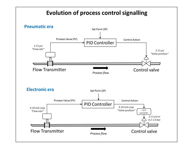
The 4-20 mA convention was born in the 1950s out of the earlier highly successful 3-15 psi pneumatic control signal standard, when electronics became cheap and reliable enough to emulate the older standard electrically. The 3-15 psi standard had the same features of being able to power some remote devices, and have a "live" zero. However the 4-20 mA standard was better suited to the electronic controllers then being developed.
The transition was gradual and has extended into the 21st century, due to the huge installed base of 3-15 psi devices. As the operation of pneumatic valves over motorised valves has many cost and reliability advantages, pneumatic actuation is still an industry standard. To allow the construction of hybrid systems, where the 4-20 mA is generated by the controller, but allows the use of pneumatic valves, a range of current to pressure (I to P) converters are available from manufacturers. These are usually located locally to the control valve and convert 4-20 mA t0 3-15 psi (or (0.2 - 1.0 bar). This signal is then fed to the valve actuator or more commonly, a pneumatic positioner. The positioner is a dedicated controller which has a mechanical linkage to the actuator movement. This ensures that problems of friction are overcome and the valve control element moves to the desired position. It also allows the use of higher air pressures for valve actuation.
With the development of cheap industrial micro-processors, "smart" valve positioners have become available since the mid-1980s and are very popular for new installations. These include an I to P converter, plus valve position and condition monitoring. These latter are fed back over the current loop to the controller, using such as the HART protocol.
Long circuits
Analog current loops were historically occasionally carried between buildings by dry pairs in telephone cables leased from the local telephone company. 4–20 mA loops were more common in the days of analog telephony. These circuits require end-to-end direct current (DC) continuity, and unless a dedicated wire pair was hardwired, their use ceased with the introduction of semiconductor switching. DC continuity is not available over a microwave radio, optical fibre, or a multiplexed telephone circuit connection. Basic DC circuit theory shows that the current is the same all along the line. It was common to see 4–20 mA circuits that had loop lengths in miles or circuits working over telephone cable pairs that were longer than ten thousand feet end-to-end. There are still legacy systems in place using this technology. In Bell System circuits, voltages up to 125 VDC were employed.
Discrete control
Discrete control functions can be represented by discrete levels of current sent over a loop. This would allow multiple control functions to be operated over a single pair of wires. Currents required for a specific function vary from one application or manufacturer to another. There is no specific current that is tied to a single meaning. It is almost universal that 0 mA indicates the circuit has failed. In the case of a fire alarm, 6 mA could be normal, 15 mA could mean a fire has been detected, and 0 mA would produce a trouble indication, telling the monitoring site the alarm circuit had failed. Some devices, such as two-way radio remote control consoles, can reverse the polarity of currents and can multiplex audio onto a DC current.
These devices can be employed for any remote control need a designer might imagine. For example, a current loop could actuate an evacuation siren or command synchronized traffic signals.
Two-way radio use
Current loop circuits are one possible way used to control radio base stations at distant sites. The two-way radio industry calls this type of remote control DC remote. This name comes from the need for DC circuit continuity between the control point and the radio base station. A current loop remote control saves the cost of extra pairs of wires between the operating point and the radio transceiver. Some equipment, such as the Motorola MSF-5000 base station, uses currents below 4 mA for some functions. An alternative type, the tone remote, is more complex but requires only an audio path between control point and base station.
For example, a taxi dispatch base station might be physically located on the rooftop of an eight-story building. The taxi company office might be in the basement of a different building nearby. The office would have a remote control unit that would operate the taxi company base station over a current loop circuit. The circuit would normally be over a telephone line or similar wiring. Control function currents come from the remote control console at the dispatch office end of a circuit. In two-way radio use, an idle circuit would normally have no current present.
In two-way radio use, radio manufacturers use different currents for specific functions. Polarities are changed to get more possible functions over a single circuit. For example, imagine one possible scheme where the presence of these currents cause the base station to change state:
This circuit is polarity-sensitive. If a telephone company cable splicer accidentally reversed the conductors, selecting channel 2 would lock the transmitter on.
Each current level could close a set of contacts, or operate solid-state logic, at the other end of the circuit. That contact closure caused a change of state on the controlled device. Some remote control equipment could have options set to allow compatibility between manufacturers. That is, a base station that was configured to transmit with a +18 mA current could have options changed to (instead) make it transmit when +6 mA was present.
In two-way radio use, AC signals were also present on the circuit pair. If the base station were idle, receive audio would be sent over the line from the base station to the dispatch office. In the presence of a transmit command current, the remote control console would send audio to be transmitted. The voice of the user in the dispatch office would be modulated and superimposed over the DC current that caused the transmitter to operate.