
 | ||
A common-path interferometer is class of interferometer in which the reference beam and sample beams travel along the same path. Examples include the Sagnac interferometer, the point diffraction interferometer, and the Zernike phase contrast interferometer. A common-path interferometer is generally more resilient to environmental vibrations than a "double path interferometer" such as the Michelson interferometer or the Mach-Zehnder interferometer. Although travelling along the same path, the reference and sample beams may travel along opposite directions, or they may travel along the same direction but with the same or different polarization.
Contents
- Sagnac
- Point diffraction
- Lateral shearing
- Fresnels biprism
- Zero area Sagnac
- Scatterplate
- Other configurations
- References
Double path interferometers are highly sensitive to phase shifts or length changes between the reference and sample arms. Because of this, double path interferometers have found wide use in science and industry for the measurement of small displacements, refractive index changes, surface irregularities and the like. There are applications, however, in which sensitivity to relative displacement or refractive index differences between reference and sample paths is not desirable; alternatively, one may be interested in the measurement of some other property.
Sagnac
Sagnac interferometers are totally unsuited for measuring lengths or length changes. In a Sagnac interferometer, both beams emerging from the beamsplitter simultaneously go around all four sides of a rectangle in opposite directions and recombine at the original beamsplitter. The result is that a Sagnac interferometer is, to first order, completely insensitive to any movement of its optical components. Indeed, in order to make the Sagnac interferometer useful for measuring phase changes, the beams of the interferometer must be separated slightly so that they no longer follow a perfectly common path. Even with a slight beam separation, Sagnac interferometers offer excellent contrast and fringe stability. Two basic topologies of the Sagnac interferometer are possible, differing in whether there are an even or odd number of reflections in each path. In a Sagnac interferometer with an odd number of reflections, such as the one illustrated, the wavefronts of the oppositely traveling beams are laterally inverted with respect to each other over most of the light path, so the topology is not strictly common-path.
The best known use of the Sagnac interferometer lies in its sensitivity to rotation. The first accounts of the effects of rotation on this form of interferometer were published in 1913 by Georges Sagnac, who mistakenly believed that his ability to detect a "whirling of the ether" disproved relativity theory. The sensitivity of present-day Sagnac interferometers far exceeds that of Sagnac's original arrangement. The sensitivity to rotation is proportional to the area circumscribed by the counter-rotating beams, and fibre optic gyroscopes, present-day descendants of the Sagnac interferometer, use thousands of loops of optical fibre rather than mirrors, such that even small to medium-sized units easily detect the rotation of the Earth. Ring laser gyroscopes (not illustrated) are another form of Sagnac rotation sensor that have important applications in inertial guidance systems.
Because of their exceptional contrast and fringe stability, interferometers using the Sagnac configuration played an important role in experiments leading to Einstein's discovery of special relativity, and in the subsequent defense of relativity against theoretical and experimental challenges. For example, one year before their famous experiment of 1887, Michelson and Morley (1886) performed a repeat of the Fizeau experiment of 1851, replacing Fizeau's setup with an even-reflection Sagnac interferometer of such high stability, that even placing a lighted match in the light path did not cause artifactual fringe displacement. In 1935, Gustaf Wilhelm Hammar disproved a theoretical challenge to special relativity that attempted to explain away the null results of Michelson–Morley–type experiments as being mere artifact of aether-dragging, using an odd-reflection Sagnac interferometer. He could operate this interferometer in the open, on a high hilltop with no temperature control, yet still achieve readings of 1/10 fringe accuracy.
Point diffraction
Another common-path interferometer useful in lens testing and fluid flow diagnostics is the point diffraction interferometer (PDI), invented by Linnik in 1933. The reference beam is generated by diffraction from a small pinhole, about half the diameter of the Airy disk, in a semitransparent plate. Fig. 1 illustrates an aberrated wavefront focused onto the pinhole. The diffracted reference beam and the transmitted test wave interfere to form fringes. The common-path design of the PDI brings to it a number of important advantages. (1) Only a single laser path is required rather than the two paths required by the Mach-Zehnder or Michelson designs. This advantage can be very important in large interferometric setups such as in wind tunnels that have long optical paths through turbulent media. (2) The common-path design uses fewer optical components than double path designs, making alignment much easier, as well as reducing cost, size, and weight, especially for large setups. (3) While the accuracy of a double path design is dependent on the precision with which the reference element is figured, careful design enables the generated reference beam of the PDI to be of guaranteed precision. A disadvantage is that the amount of light getting through the pinhole depends on how well the light can be focused onto the pinhole. If the incident wavefront is severely aberrated, very little light may get through. The PDI has seen use in various adaptive optics applications.
Lateral shearing
Lateral shearing interferometry is a self-referencing method of wavefront sensing. Instead of comparing a wavefront with a separate path reference wavefront, lateral shearing interferometry interferes a wavefront with a shifted version of itself. As a result, it is sensitive to the slope of a wavefront, not the wavefront shape per se. The illustrated plane parallel plate interferometer has unequal path lengths for the test and reference beams; because of this, it must be used with highly monochromatic (laser) light. It is normally used without any coating on either surface, so as to minimize ghost reflections. An aberrated wavefront from a lens under test is reflected from the front and back of the plate to form the interference pattern. Variations on this basic design allow testing of mirrors. Other forms of lateral shearing interferometer, based on the Jamin, Michelson, Mach–Zehnder, and other interferometer designs, have compensated paths and may be used with white light. Besides optical testing, applications of lateral shearing interferometry have included thin film analysis, mass and thermal diffusion in transparent materials, refractive index and gradient of refractive index measurement, collimation testing, and adaptive optics. Shearing interferometers, a general framework which includes the lateral shearing, Hartmann, Shack-Hartmann, rotational shearing, folding shearing, and aperture masking interferometers, are used in most of the wavefront sensors industrially developed.
Fresnel's biprism
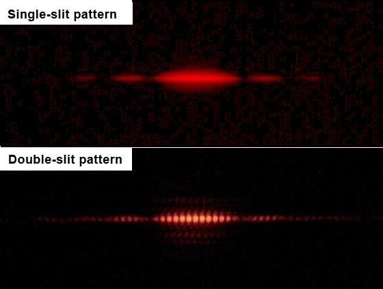
From the modern perspective, the result of Young's double slit experiment (see Fig. 2) clearly points towards the wave nature of light, but such was not the case in the early 1800s. Newton, after all, had observed what are now recognized as diffraction phenomena, and wrote on them in his Third Book of Optics, interpreting them in terms of his corpuscular theory of light. Young's contemporaries raised objections that his results could simply represent diffraction effects from the edges of the slits, no different in principle than the fringes that Newton had previously observed. Augustin Fresnel, who supported the wave theory, performed a series of experiments to demonstrate interference effects that could not be simply explained away as being the result of edge diffraction. The most notable of these was his use of a biprism to create two virtual interfering sources by refraction.
An electron version of the Fresnel biprism is used in electron holography, an imaging technique that photographically records the electron interference pattern of an object. The hologram can then be illuminated by a laser resulting in a greatly magnified image of the original object, although the current preference is for numerical reconstruction of the holograms. This technique was developed to enable greater resolution in electron microscopy than is possible using conventional imaging techniques. The resolution of conventional electron microscopy is not limited by electron wavelength, but by the large aberrations of electron lenses.
Fig. 3 shows the basic arrangement of an interference electron microscope. The electron biprism consists of a fine, positively charged electric filament (represented as a dot in the figure) bracketed by two plate electrodes at ground potential. The filament, generally not more than 1 μm in diameter, is usually a gold-coated quartz fiber. By placing the specimen off-axis in the electron beam, the diffracted specimen wavefront and the reference wavefront combine to create the hologram.
Zero-area Sagnac
The Laser Interferometer Gravitational-Wave Observatory (LIGO) consisted of two 4-km Michelson-Fabry-Pérot interferometers, and operated at a power level of about 100 watts of laser power at the beam splitter. A currently ongoing upgrade to Advanced LIGO will require several kilowatts of laser power, and scientists will need to contend with thermal distortion, frequency variation of the lasers, mirror displacement and thermally induced birefringence.
A variety of competing optical systems are being explored for third generation enhancements beyond Advanced LIGO. One of these competing topologies has been the zero-area Sagnac design. As noted above, Sagnac interferometers are, to first order, insensitive to any static or low-frequency displacement of their optical components, nor are the fringes affected by minor frequency variation in the lasers or birefringence. A zero-area variant of the Sagnac interferometer has been proposed for third generation LIGO. Fig. 1 shows how by directing the light through two loops of opposite sense, an effective area of zero is obtained. This variant of the Sagnac interferometer is hence insensitive to rotation or low frequency drift of its optical components, while maintaining a high sensitivity to transient events of astronomical interest. However, many considerations are involved in the choice of an optical system, and despite the zero-area Sagnac's superiority in certain areas, there is as yet no consensus choice of optical system for third generation LIGO.
Scatterplate
A common path alternative to the Twyman–Green interferometer is the scatterplate interferometer, invented by J.M. Burch in 1953. The Twyman–Green interferometer, a double path interferometer, is a variant of the Michelson interferometer that is commonly used to test the precision of optical surfaces and lenses. Since reference and sample paths are divergent, this form of interferometer is extremely sensitive to vibration and to atmospheric turbulence in the light paths, both of which interfere with the optical measurements. Precision measurements of an optical surface are also extremely dependent on the quality of the auxiliary optics.
Because the scatterplate interferometer is a common-path interferometer, the reference and test paths are automatically matched so that a zero order fringe can be easily obtained even with white light. It is relatively insensitive to vibration and turbulence, and the quality of the auxiliary optics is not as critical as in a Twyman-Green setup. Fringe contrast, however, is lower, and a characteristic hotspot may make the scatterplate interferometer unsuitable for various purposes. A variety of other common-path interferometers useful for optical testing have been described.
Fig. 1 shows the interferometer set up to test a spherical mirror. A scatterplate is set near the center of curvature of the mirror under test. This plate has a pattern of tiny opaque patches which are arranged on the plate with inversion symmetry but which are otherwise random in shape and distribution. (1) A certain fraction of the light passes directly through the scatterplate, is reflected by the mirror, but then is scattered as it encounters the scatterplate for the second time. This direct-scattered light forms the reference beam. (2) A certain fraction of the light is scattered as it passes through the scatterplate, is reflected by the mirror, but then passes directly through the scatterplate as it encounters the scatterplate for the second time. This scattered-direct light forms the test beam, which combines with the reference beam to form interference fringes. (3) A certain fraction of the light passes directly through the scatterplate on both of its encounters. This direct-direct light generates a small, undesirable hotspot. (4) A certain fraction of the light is scattered on both encounters with the scatterplate. This scattered-scattered light lowers the overall contrast of the interference pattern.
Other configurations
Other common-path interferometer configurations have been described in the literature, such as the double-focus interferometer and the Saunders's prism interferometer, and many others. Common-path interferometers have proven useful in a wide variety of applications including optical coherence tomography, digital holography, and the measurement of phase delays. Their relative resilience to environmental vibration is a common outstanding feature, and they can sometimes be used when no reference beam is available; however, depending on their topology, their interference patterns may be more complicated to interpret than those generated by double path interferometers.