
 | ||
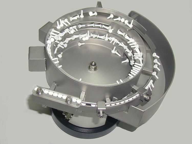
Vibratory bowl feeders are common devices used to feed individual component parts for assembly on industrial production lines. They are used when a randomly sorted bulk package of small components must be fed into another machine one-by-one, oriented in a particular direction.
Contents
Vibratory feeders rely on the mechanical behaviour of a part, such that when gently shaken down a conveyor chute that is shaped to fit the part, they will gradually be shaken so that they are all aligned. They thus leave the feeder's conveyor one-by-one, all in the same orientation. This conveyor then leads directly to the following assembly or packing machine.
Orientation relies on the shape and mechanical behaviour of an object, particular the position of its centre of mass in relation to its centre of volume. It thus works well for parts such as machine screws, with rotational symmetry and a clear asymmetry to one heavy end. It does not work for entirely symmetrical shapes, or where orientation depends on a feature such as colour. The ramps within a bowl feeder are specifically designed for each part, although the core mechanism is re-used across different parts.
The exit orientation of a bowl feeder depends on the part's shape and mass distribution. Where this is not the orientation needed for the following assembly step, a feeder is often followed by a twisted conveyor that turns the part over, as needed.
With increasing integration across an entire production process, the need for feeders is sometimes reduced by supplying the components on tape packages or similar, that keep them oriented the same way during shipping and storage. These are most common in fields such as electronics, where components must be used in a particular orientation, but this cannot be detected mechanically.
Vibratory feeders, commonly known as a bowl feeder, are self-contained devices, consisting of a specially shaped bowl designed to orient the parts to a specific orientation. A vibrating drive unit, upon which the bowl is mounted and a variable-amplitude control box controls the bowl feeder. Usually included is an out feed accumulation track (linear or gravity) to convey parts along and discharge into the assembly machine comes in many shapes and sizes. The drive unit, available in both electromagnetic and pneumatic drives, vibrates the bowl, forcing the parts to move up a circular, inclined track. The tooling (hand made) is designed to sort and orient the parts in to a consistent, repeatable position. The track length, width, and depth are carefully chosen to suit each application, component shape and size. Special bowl and track coatings are applied according to shape size and material of the component which aids traction, damage to the product and lower acoustic levels. A variable speed control box is used for controlling the vibration speed of the bowl feeder, and can control the flow of parts to the out feed track via sensors.
Vibratory feeders are utilized by all industries including, the pharmaceutical, automotive, electronic, cosmetic, food, Fast Moving Consumable Goods (FMCG), packaging and metalworking industries. It also serves other industries such as glass, foundry, steel, construction, recycling, pulp and paper, and plastics. Vibratory feeders offer a cost-effective alternative to manual labour, saving manufacturer’s time and labour costs. Several factors must be considered when selecting a parts feeder, including the industry, application, material properties and product volume.
History/Inventor