
 | ||
AES3 (also known as AES/EBU) is a standard for the exchange of digital audio signals between professional audio devices. AES3 was jointly developed by the Audio Engineering Society (AES) and the European Broadcasting Union (EBU). An AES3 signal can carry two channels of PCM audio over several transmission media including balanced lines, unbalanced lines, and optical fiber. It was published in 1985 and has been revised in 1992 and 2003.
Contents
- History and development
- Hardware connections
- IEC 60958 Type IBalanced XLR
- IEC 60958 Type IIUnbalanced RCA
- IEC 60958 Type III OpticalFiber F05TOSLINK
- Other connections
- Relation to SPDIF
- Protocol
- Synchronisation preamble
- Channel status word
- Embedded timecode
- References
AES3 has been incorporated into the International Electrotechnical Commission's standard IEC 60958, and is available in a consumer-grade variant known as S/PDIF.
History and development
The development of standards for digitising analog audio, as used to interconnect both professional and domestic audio equipment, began in the late 1970s in a joint effort between the Audio Engineering Society and the European Broadcasting Union, and culminated in the publishing of AES3 in 1985. Early on, the standard was frequently known as AES/EBU. Both AES and EBU versions of the standard exist. Variants using different physical connections—essentially consumer versions of AES3 for use within the domestic "Hi-Fi" environment using connectors more commonly found in the consumer market—are specified in IEC 60958. These variants are commonly known as S/PDIF.
The standard has been revised in 1992 and 2003 and is published in AES and EBU versions. Worldwide, it is the most commonly used method for digitally interconnecting audio equipment.
Hardware connections
The AES3 standard parallels part 4 of the international standard IEC 60958. Of the physical interconnection types defined by IEC 60958, three are in common use.
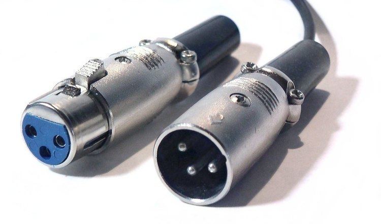
IEC 60958 Type I—Balanced, XLR
Type I connections use balanced, 3-conductor, 110-ohm twisted pair cabling with XLR connectors. Type I connections are most often used in professional installations and are considered the AES3 standard connector. The hardware interface is usually implemented using RS-422 line drivers and receivers.
IEC 60958 Type II—Unbalanced, RCA
Type II connections use unbalanced, 2-conductor, 75-ohm coaxial cable with RCA connectors. Type II connections are often used in most consumer audio installations and are often called coaxial S/PDIF connections.
IEC 60958 Type III Optical—Fiber, F05/TOSLINK
Type III Optical connections use optical fiber—usually plastic, but occasionally glass—with F05 connectors, which are more commonly known by their Toshiba brand name, TOSLINK. Like Type II, Type III Optical connections are also used in consumer audio installations and are often called optical S/PDIF connections.
Other connections
The AES-3id standard defines a 75-ohm BNC electrical variant of AES3. This uses the same cabling, patching and infrastructure as analogue or digital video, and is thus common in the broadcast industry.
AES3 digital audio format can also be carried over an Asynchronous Transfer Mode network. The standard for packing AES3 frames into ATM cells is AES47.
For information on the synchronization of digital audio structures, see the AES11 standard. The ability to insert unique identifiers into an AES3 bit stream is covered by the AES52 standard.
Relation to S/PDIF
The precursor of the IEC 60958 Type II specification was the Sony/Philips Digital Interface, or S/PDIF. S/PDIF and AES3 are similar in many ways and are interchangeable at the protocol level, but at the physical level they specify different electrical signaling levels and impedances, which may be significant in some applications.
Protocol
The low-level protocol for data transmission in AES3 and S/PDIF is largely identical, and the following discussion applies for S/PDIF, except as noted.AES3 was designed primarily to support stereo PCM encoded audio in either DAT format at 48 kHz or CD format at 44.1 kHz. No attempt was made to use a carrier able to support both rates; instead, AES3 allows the data to be run at any rate, and encoding the clock and the data together using biphase mark code (BMC).
The basic unit of transmission is the frame. Frames contain 64 time slots and are produced once per sample time. This determines the clock rate.
At the highest level, each 192 consecutive frames are grouped into an audio block. While samples repeat each frame time, metadata is only transmitted once per audio block.
Each frame is divided into two 32-time-slot subframes each containing one sample; the subframes are used for the channels: A (left) and B (right). Each subframe consists of 32 time slots, each of which contains either one bit encoded with biphase mark code or a special synchronisation preamble. In each subframe, audio data may use up to 24 bits.
At the default 48 kHz sample rate, there are 250 audio blocks per second, and 3,072 kilobits per second with a biphase clock of 6.144 MHz
The 32 time slots of each subframe are used as following:
Synchronisation preamble
This is a specially coded preamble that identify the subframe and its position within the audio block. They are not normal BMC-encoded data bits, although they do still have zero DC bias.
Three preambles are possible :
They are called X, Y, Z in the AES3 standard; and M, W, B in IEC 958 (an AES extension).
The 8-bit preambles are transmitted in time allocated to the first four time slots of each subframe (time slots 0 to 3). Any of the three marks the beginning of a subframe. X or Z marks the beginning of a frame, and Z marks the beginning of an audio block.
| 0 | 1 | 2 | 3 | | 0 | 1 | 2 | 3 | Time slots _____ _ _____ _ / _____/ _/ _____/ _/ Preamble X _____ _ ___ ___ / ___/ ___/ _____/ _/ Preamble Y _____ _ _ _____ / _/ _____/ _____/ _/ Preamble Z ___ ___ ___ ___ / ___/ ___/ ___/ ___/ All 0 bits BMC encoded _ _ _ _ _ _ _ _ / _/ _/ _/ _/ _/ _/ _/ _/ All 1 bits BMC encoded | 0 | 1 | 2 | 3 | | 0 | 1 | 2 | 3 | Time slotsIn two-channel AES3, the preambles form a pattern of ZYXYXYXY…, but it is straightforward to extend this structure to additional channels (more subframes per frame), each with a Y preamble, as is done in the MADI protocol.
Channel status word
As stated before there is one channel status bit in each subframe, making one 192 bit word for each channel in each block. This 192 bit word is usually presented as 192/8 = 24 bytes. The contents of the channel status word are completely different between the AES3 and S/PDIF standards, although they agree that the first channel status bit (byte 0 bit 0) distinguishes between the two. In the case of AES3, the standard describes in detail how the bits have to be used. Here is a summary of the channel status word:
Embedded timecode
SMPTE timecode timestamp data can be embedded within AES3 digital audio signals. It can be used for synchronization and for logging and identifying audio content. According to John Ratcliff's Timecode: A user's guide, it is embedded as a 32-bit binary word in bytes 18 to 21 of the channel status data.