
 | ||
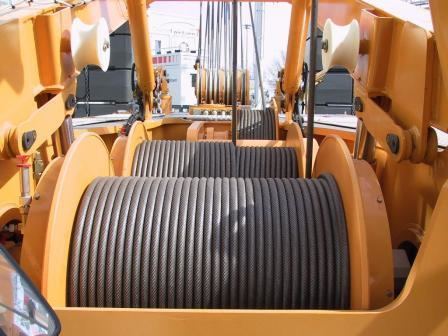
Wire rope spooling-Technology is the technology to prevent wire rope getting snagged when spooled especially in multiple layers on a drum.
Contents
History
Ever since the development of wire rope, comprising multiple wire strands, spooling the wire has presented technical challenges. When wrapped in multiple layers, the upper layers have a tendency to crush the lower layers, while the lower layers have a tendency to pinch upper layers. The rubbing of rope against rope also has a tendency to cause wear. These problems were addressed by Frank L. LeBus Sr., a supplier of drilling equipment to the oilfields of Texas, USA, who in 1937, patented the use of a groove bar on hoisting drums to guide the spooling of rope. Grooved shape steel segments were simply welded or screwed to existing plain steel drums. Ever since then, drum groovings have been widely used to guide the spooling of wire rope onto and off winch drums. Introducing a continuous helical groove onto the drum, like the thread of a screw, provides a way to guide the rope when spooling onto or off a drum. However this has been shown to work effectively only when the rope is wrapped in a single layer. When the rope is wrapped in multiple layers, problems remain. Frank LeBus introduced a grooving pattern that put the groove parallel to the flanges of the drum, except for a single slanted section across the drum face to act as crossover point, moving the rope along by the width of the groove with every revolution.
While the Lebus family business continues to produce this equipment today, patents have expired and other winch manufacturers also use the Lebus system. Any drum with a parallel groove and two cross-over points is often generically called ‘a Lebus drum’, regardless of the manufacturer.
Applications
The multilayer wire rope spooling system has undergone continuous refinement over the years and adapted for any application where long lengths of steel wire ropes must be wrapped in multiple layers quickly and smoothly. Examples include:
System advantages
With the parallel groove system, rope wear is considerably reduced in multilayer spooling.
When the first layer has filled the drum, the second layer then travels back across the drum with each wrap of rope sitting precisely along the groove of two wraps of the first layer. With parallel grooving it is possible to calculate the exact forces that the rope imposes on the drum because the spooling is controlled.
Cross winding is reduced to approximately 20 percent of the circumference of the drum, and 80 percent remains parallel to the flanges in the inner layer rope groove. This parallel grooving evenly distributes the load between the individual layers and has been show to increase substantially – by more than 500percent, tests have shown – the life of the wire rope. The system has been used to mount ropes up.
In offshore applications, huge lengths of rope are often housed on drums. The anchor winches on Saipem’s Semac 1 pipe laying barge, for example, each hold 2,800 metres of 76mm (3 inch) diameter wire rope in 14 layers. Saipem’s Castorone, the world’s largest pipe laying vessel uses a wire rope that is 3,850m long and 152mm in diameter. It weighs 420t. The rope is pulled by capstan and stored on a massive Rema traction winches that feature the parallel grooving system, with an approximately back tension of 40t on the capstan.
Required operating parameters
To maximise the benefits of the parallel grooving system, certain operating conditions are required. These include:
Every system should be tailored to the application for which it is used. The groove pattern is engineered to suit the rope's length, diameter and construction type.
In any multi-layer spooling application it is important that when the rope is first installed on the drum, it is done so under tension to avoid any slack on inner layers that can be crushed or nicked against the groove walls by outer layers.
The fleet angle is defined as the largest angle of the rope between the first sheave and the drum flange, relative to the centre line of the drum. With all type of drums, the rope is subject to a fleet angle which impacts on its behaviour and affects lifespan. Fleet angle should be between 0.25° and 1.25°, depending on the rope construction. The fleet angle can be varied by moving the first sheave closer to or further away from the drum. If the sheave is too close to the drum, the fleet angle will be greater than 1.25°; if it is too far away, the fleet angle will be less than 0.25°.
Accessories
Sometimes it is not possible to achieve the optimum fleet angle. Where there is no space to rig a sheave the requisite distance from the drum, two additional spooling devices are available. One is a fleet angle compensator, which is driven automatically by the rope tension. The other is a level winder that is mechanically driven. Both offer a solution to guide the cable along the drum between flanges, but each has its advantages and disadvantages.
Fleet angle compensator
The fleet angle compensator (FAC) is driven by the movement of the wire rope as it goes through the crossover sections of the drum. As the rope winds or unwinds, the FAC shaft automatically oscillates slowly, allowing its sheave to slide back and forth across the shaft to maintain an optimum fleet angle and guide the rope smoothly onto the drum.
Screw level winder
Level winders can be hydraulically or electrically driven and computer controlled, or they can be simple mechanical devices. A mechanical level winder comprises a main shaft (the lead screw) with helical screw grooving along which the rope feeder travels. The rope feeder housing includes two vertical roller bars and one horizontal roller, or alternatively a wire rope sheave. The lateral movement of the housing is generated by a chain drive sprocket ratio between drum and lead screw, as shown in the image. The automatic level winder fitted is designed and engineered to be compatible with the grooving on the drum. Alternatively, a sheave can be integrated and installed within the housing frame. In this case, the system can be set up anywhere around the drum. Oceanographic installations that spool rope up to 46 layers have demonstrated that level winders give synchronized and controlled spooling in the harshest, most testing conditions.
Split sleeves
Grooving systems for multilayer spooling can be carved onto steel shells that are mounted onto old drums, by either bolting or welding, as an outer sleeve. Called split sleeves, they can be retrofitted onto old drums or mounted on new drums to allow a future change of application.