
 | ||
A Williamson amplifier refers to a type of vacuum tube (valve) amplifier whose circuit design uses the same principles as a design published by D.T.N. Williamson. Williamson proposed the standard which became generally accepted as the target figure for high-quality audio power amplifiers, for less than 0.1% total harmonic distortion at full rated power output.
Contents
Design
In April and May 1947, the British magazine Wireless World published a pair of articles by D.T.N. Williamson, under the title "Design for a High-quality Amplifier." The design, which became known as the "Williamson Amplifier", was an early example of high fidelity in an audio amplifier (the commercial LEAK "Point One" Type 15 amplifier of 1945 pre-dates it). The design became widely known for the notably high quality of its audio reproduction, and many Williamson amplifiers were built, both for own use and for sale; follow-up articles were published, with a slightly revised design
The simplicity of the design shows in the circuit diagram. The overall negative feedback is clearly seen to be applied by the resistor R25 from the secondary of the output transformer to the cathode of the input V1. While the output transformer is represented simply by the appropriate circuit symbol, it is a component which must be designed with great care.
Printed circuit boards (PCBs) were rarely used at the time (they were less necessary than they became for complex semiconductor circuits, due to the relative simplicity of circuits and the use of large socketed components); point-to-point wiring was used.
Description
The Williamson amplifier was of symmetric push-pull design and used negative feedback and a specially designed output transformer to produce lower levels of distortion than previous designs.
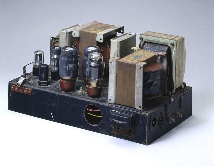
The design used triodes as phase inverters and drivers. The original output stages used triode-connected KT66 tetrodes, although a 6L6, with slightly lower output, could be used.
A notable characteristic of the design was the use of a negative feedback loop enclosing the whole amplifier, including the output transformer, rather than separate feedback around individual stages. This approach to feedback requires care to be taken to avoid excessive phase-shift around the feedback loop (the transformer being a particular problem), to avoid the feedback becoming positive at any frequency, which would cause undesirable oscillation.
Earlier designs used transformers to couple the output signal from one stage to the next. A transformer with a centre-tapped secondary was used as a simple method to drive the push-pull output valves in anti-phase from the previous single-ended stage.
Signal transformers are a source of distortion; if the transformers are not included in the feedback loop, this distortion is not corrected. They also produce large, frequency-dependent phase shifts at higher frequencies, making feedback loops including the transformers problematical.
Williamson eliminated all transformers except the output transformer (unavoidable for matching the high valve impedance to the low loudspeaker impedance) by using capacitor coupling between stages, and a split-load valve voltage amplifier stage ("phase splitter"), again capacitor-coupled, to provide antiphase signal inputs to the symmetrical push-pull output stages. There was thus a single signal transformer in the circuit; with careful design of the transformer and the feedback network significant negative feedback could be used before the onset of instability. A 1993 book by Linsley Hood discusses the characteristics of the Williamson amplifier design and its performance compared to earlier and later designs.
The Williamson design demonstrates the maturity that tube amplification had reached by the late 1940s. Other than the British Mullard 5-10 circuit and David Hafler's Dynaco ST-70, there was little improvement in the fundamentals. One improvement that was widely used was an output transformer with additional taps allowing use of Blumlein's distributed load or ultra-linear technique, which allowed the output stage, before applying feedback, to operate at a power intermediate between that available from a triode and the significantly higher power from a pentode or beam tetrode, with distortion better than either.
Valve lineup
The valves used in the original 1947 design were four single triodes (the L63), a directly heated U52 rectifier, and a pair of KT66 beam tetrodes, all from the Marconi-Osram Valve (MOV) Company. In D.T.N. Williamson's 1949 update in Wireless World several small changes to the circuit were suggested along with a list of alternative triodes and the more significant change in rectifier to the indirectly heated Cossor 53KU or 5V4 to prevent "a damaging voltage surge when the amplifier is switched on".
Williamson said there "is no exact equivalent for the Osram type KT66, and its use is recommended where possible. When the equipment is to be used overseas, the KT66 may be difficult to obtain, and the 6L6 glass and metal types may be regarded as direct replacements, with the proviso that the total anode and screen dissipation should be reduced from 25 W to 21.5 W by reducing the total current from 125 mA to 110 mA by adjustment of R21."
Follow-up articles in Wireless World from October 1949 to May 1952 included circuits for Tone controls, Radio Feeder Unit, and modifications for High-impedance Pickups and Long-playing record equalisation. The valves used are:
Historical significance
Even two decades later, the Williamson amplifier's performance was a standard of comparison for innovative successor developments, including well-known semiconductor audio amplifiers such as Linsley Hood's transistor "Simple Class-A Amplifier", published in 1969, with explicit discussion of Williamson's criterion.