
 | ||
Wind waves can be measured by several radar remote sensing techniques. Several instruments based on a variety of different concepts and techniques are available to the user and these are all often called wave radars. This article (see also Grønlie 2004), gives a brief description of the most common ground-based radar remote sensing techniques.
Contents
- Terms and definitions
- The wave radar performance is highly dependent on
- Remote sensing techniques
- Microwave range finders
- Marine navigation radars
- The range gated pulsed Doppler microwave radar
- The dual frequency microwave radar
- The HF radar
- References
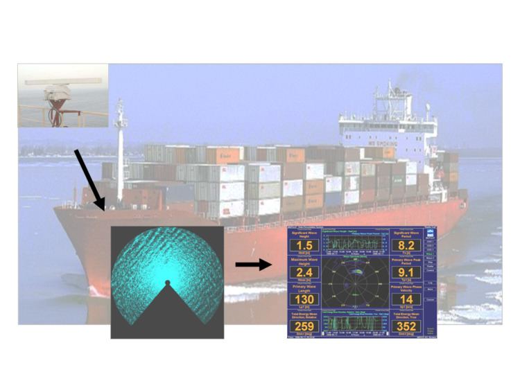
Instruments based on radar remote sensing techniques have become of particular interest in applications where it is important to avoid direct contact with the water surface and avoid structural interference. A typical case is wave measurements from an offshore platform in deep waters with the presence of high currents making the mooring of a wave buoy enormously difficult. Another interesting case is a ship under way where having instruments in the sea is highly impractical and interference from the ship's hull must be avoided.
Terms and definitions
Basically there are two different classes of radar remote sensors for ocean waves.
Microwave radars may be used in two different modes;
The radar footprint (the radial and azimuthal extent of the surface area to be illuminated by the radar) must be small in comparison with all ocean wavelength of interest. The radar spatial resolution is determined by the bandwidth of the radar signal (see radar signal characteristics) and the beamwidth of the radar antenna.
The beam of a microwave antenna is dispersive, consequently the resolution becomes a function of range. The beam of an IR radar (laser) is non dispersive, the radar footprint is therefore independent of range.
HF radars utilize the Bragg scattering mechanism and do always operate at very low grazing angles. Due to the low frequency of operation the radar waves are backscattered directly from the gravity waves and surface ripple need not be present.
Radar transceivers may be coherent or non-coherent. Coherent radars measure Doppler-modulation as well as amplitude modulation, while non-coherent radars only measure amplitude modulation. Consequently, a non-coherent radar echo contains less information about the sea surface properties. Examples of non-coherent radars are conventional marine navigation radars.
The radar transmitter waveform may be either unmodulated continuous wave, modulated or pulsed. An unmodulated continuous wave radar has no range resolution, but can resolve targets on the basis of different velocity, while a modulated or pulsed radar can resolve echoes from different ranges. The radar waveform plays a very important role in radar theory (Plant and Shuler, 1980).
The wave radar performance is highly dependent on
Remote sensing techniques
An excellent survey of different radar techniques for remote sensing of waves is given by Tucker (1991).
Microwave range finders
Microwave range finders also operate in vertical mode at GHz frequencies and is not as affected by fog and water spray as the laser altimeter. A continuous wave frequency modulated (CWFM) or pulsed radar waveform is normally used to provide range resolution. The beam is dispersive, hence the size of the footprint increases linearly with range.
One example of a microwave range finder is the Miros SM-094 which is designed for wave and water level (and tide) measurements. This sensor is applied as air gap (bridge clearance) sensor in NOAAs PORTS system. Another example is the WaveRadar REX which is a derivative of a Rosemount tank radar.
An array of three vertical radars in a triangular configuration can be used to measure a directional wave spectrum. Algorithms and signal processing software similar to what is used in the processing of heave, pitch, roll buoys. A commercial system called “Directional WaveGuide” is available from the Dutch companies Enraf and Radac.
Marine navigation radars
Marine navigation radars (X band) provide sea clutter images which contain a pattern resembling a sea wave pattern. By digitizing the radar video signal it can be processed by a digital computer. Sea surface parameters may be calculated on the basis of these digitized images. The marine navigation radar operates in low grazing angle mode and wind generated surface ripple must be present. The marine navigation radar is non-coherent and is a typical example of an indirect wave sensor, because there is no direct relation between wave height and radar back-scatter modulation amplitude. An empirical method of wave spectrum scaling is normally employed. Marine navigation radar based wave sensors are excellent tools for wave direction measurements. A marine navigation radar may also be a tool for surface current measurements. Point measurements of the current vector as well as current maps up to a distance of a few km can be provided (Gangeskar, 2002). Miros WAVEX has its main area of application as directional wave measurements from moving ships. Another example of a marine radar based system is OceanWaves WaMoS II.
The range gated pulsed Doppler microwave radar
The range gated pulsed Doppler microwave radar operates in low grazing angle mode. By using several antennas it may be used as a directional wave sensor, basically measuring the directional spectrum of the horizontal water particle velocity. The velocity spectrum is directly related to the wave height spectrum by a mathematical model based on linear wave theory and accurate measurements of the wave spectrum can be provided under most conditions. As measurements are taken at a distance from the platform on which it is mounted, the wave field is to a small degree disturbed by interference from the platform structure.
Miros Wave and current radar is the only available wave sensor based on the range gated pulsed Doppler radar technique. This radar also uses the dual frequency technique (see below) to perform point measurements of the surface current vector
The dual frequency microwave radar
The dual frequency microwave radar transmits two microwave frequencies simultaneously. The frequency separation is chosen to give a “spatial beat” length which is in the range of the water waves of interest. The dual frequency radar may be considered a microwave equivalent of the high frequency (HF) radar (see below). The dual frequency radar is suitable for the measurement of surface current. As far as wave measurements are concerned, the back-scatter processes are too complicated (and not well understood) to allow useful measurement accuracy to be attained.
The HF radar
The HF radar CODAR SeaSonde and Helzel WERA are well established as a powerful tool for sea current measurements up to a range of 300 km. It operates in the HF and low VHF frequencies band corresponding to a radar wavelength in the range of 10 to 300m. The Doppler shift of the first order Bragg lines of the radar echo is used to derive sea current estimates in very much the same way as for the dual frequency microwave radar. Two radar installations are normally required, looking at the same patch of the sea surface from different angles. The latest generation of shore-based ocean radar can reach more than 200 km for ocean current mapping and more than 100 km for wave measurements Helzel WERA. For all ocean radars, the accuracy in range is excellent. With shorter ranges, the range resolution gets finer. The angular resolution and accuracy depends on the used antenna array configuration and applied algorithms (direction finding or beam forming). The WERA system provides the option to use both techniques; the compact version with direction finding or the array type antenna system with beam forming methods.