
 | ||
The Vienna Rectifier is a pulse-width modulation rectifier, invented in 1993 by Johann W. Kolar.
Contents
Features
Vienna Rectifier provides following features:
Topology
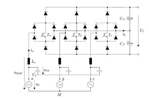
The Vienna Rectifier is a unidirectional three-phase three-switch three-level Pulse-width modulation (PWM) rectifier. It can be seen as a three-phase diode bridge with an integrated boost converter.
Applications
The Vienna Rectifier is useful wherever six-switch converters are used for achieving sinusoidal mains current and controlled output voltage, when no energy feedback from the load into the mains is required. In practice, use of the Vienna Rectifier is advantageous when space is at a sufficient premium to justify the additional hardware cost. These include:
Figure 2 shows the top and bottom views of an air-cooled 10 kW-Vienna Rectifier (400 kHz PWM), with sinusoidal input current s and controlled output voltage. Dimensions are 250mm x 120mm x 40mm, resulting in a power density of 8.5 kW/dm3. The total weight of the converter is 2.1 kg
Current and voltage waveforms
Figure 3 shows the system behavior, calculated using the power-electronics circuit simulator. Between the output voltage midpoint (0) and the mains midpoint (M) the common mode voltage u0M appears, as is characteristic in three-phase converter systems.
Current control and balance of the neutral point at the DC-side
It is possible to separately control the input current shape in each branch of the diode bridge by inserting a bidirectional switch into the node, as shown in Figure 3. The switch Ta controls the current by controlling the magnetization of the inductor. Switched on charges the inductor which drives the current through the bidirectional switch. Deactivating the switch increases causes the current to bypass the switch and flow through the freewheeling diodes Da+ and Da-. This results in a negative voltage across the inductor and drains it. This demonstrates the ability of the topology to control the current in phase with the mains voltage (PFC capability).
To generate a sinusoidal power input which is in phase with the voltage