
 | ||
A via fence, also called a picket fence, is a structure used in planar electronic circuit technologies to improve isolation between components which would otherwise be coupled by electromagnetic fields. It consists of a row of via holes which, if spaced close enough together, form a barrier to electromagnetic wave propagation.
Contents
Modern electronics have components and sub-units at high densities to achieve small size. Typically, many functions are integrated on to the same board or die. If not properly shielded from each other, many problems can result including poor frequency response, noise performance, and distortion.
Via fences are used to shield microstrip and stripline transmission lines, guard edges of printed circuit boards, shield functional circuit units from each other, and to form the walls of waveguides integrated into a planar format. Via fences are cheap and easy to implement, but use up board space and are not as effective as solid metal walls.
Purpose
Planar technologies are used at microwave frequencies and make use of printed circuit tracks as transmission lines. As well as interconnections, these lines can be used to form components of functional units such as filters and couplers. Planar lines readily couple to each other when in close proximity, an effect called parasitic coupling. The coupling is due to fringing fields spreading from the edges of the line and intersecting adjacent lines or components. This is a desirable feature within the unit where it is made use of as part of the design. It is not desirable, however, that the fields couple to adjacent units. Modern electronic devices are usually required to be small. That, and the drive to keep down costs, leads to a high degree of integration and circuit units in less than desirable proximity. Via fences are one method that can be used to reduce parasitic coupling between such units.
Amongst the many problems that can be caused by parasitic coupling are reducing bandwidth, degrading passband flatness, reducing amplifier output power, increasing reflections, worsening noise figure, causing amplifier instability, and providing undesirable feedback paths.
In stripline, via fences running parallel to the line on either side serve to tie together the groundplanes, so preventing the propagation of parallel-plate modes. A similar arrangement is used to suppress unwanted modes in metal-backed coplanar waveguide.
Structure
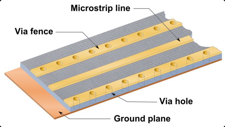
A via fence consists of a row of via holes, that is, holes that pass through the substrate and are metallised on the inside to connect to pads on the top and bottom of the substrate. In a stripline format both the top and bottom of the dielectric sheet are covered with a metal ground plane so any via holes are automatically grounded at both ends. In other planar formats such as microstrip there is a ground plane only at the bottom of the substrate. In these formats it is the usual practice to connect the top pads of the via fence with a metal track (see figure 2). This still does not completely fence off the field as can be done in stripline. In stripline the field can only propagate between the ground planes, but in microstrip it is able to leak over the top of the via fence. Nevertheless, connecting the top pads improves isolation by 6-10 dB. In some technologies it is more convenient to form the fence from conducting posts rather than vias.
Isolation can be further improved by placing a metal wall on top of the via fence. These walls commonly form part of the device enclosure. The large holes in the via fences seen in figures 1 and 5 are screw holes for clamping these walls in place. The wall casting belonging to this circuit is shown in figure 3.
The design of the fence needs to consider the size and spacing of the vias. Ideally, vias should act as short circuits, but they are not ideal and a via equivalent circuit can be modelled as a shunt inductance. Sometimes, a more complex model is required such as the equivalent circuit shown in figure 4. L1 is due to the inductance of the pads and C is the capacitance between them. R and L2 are, respectively, the resistance and inductance of the via hole metallisation. Resonances must be considered, in particular the parallel resonance of C and L2 will allow electromagnetic waves to pass at the resonant frequency. This resonance needs to be placed outside the operating frequencies of the equipment concerned. Spacing of the fences needs to be small in comparison to a wavelength (λ) in the substrate dielectric so as to make the fence appear solid to impinging waves. If too large, waves will be able to pass through the gaps. A common rule of thumb is to make the spacing less than λ/20 at the maximum operating frequency.
Applications
Via fences are used primarily at RF and microwave frequencies wherever planar formats are being applied. They are used in printed circuit technologies such as microstrip, ceramic technologies such as low temperature co-fired ceramic, monolithic microwave integrated circuits, and system-on-a-package technology. They are especially important in isolating circuit units operating at different frequencies.
Via fences can be used around the edge of a printed circuit board, an example can be seen in figure 5. This may be done to prevent electromagnetic interference with other equipment, or even to block radiation re-entering from elsewhere on the same circuit.
Via fences are also used in post-wall waveguide, also known as laminated waveguide (LWG). In LWG, two parallel via fences form the sidewalls of a waveguide. Between them, and the upper and lower groundplanes of the substrate, is an electromagnetically isolated space. There is no electrical conductor within this space, but electromagnetic waves can exist within the enclosed dielectric material of the substrate and their direction of propagation is guided by the LWG. This technology is typically used at millimetre band frequencies and consequently dimensions are quite small. Furthermore, good isolation requires that the vias are closely spaced. Typically, 60 dB isolation is required between guides, that is 30 dB per fence. A typical W band (75-110 GHz) fence specification meeting this requirement in LWG is .003-inch (76 µm) vias spaced .006 inches (150 µm) between centres. This can be challenging to manufacture, and a higher density of vias is sometimes achieved by constructing the fence from two staggered rows of vias.
Advantages and disadvantages
Via fences are cheap and convenient. When used on planar formats they require no additional processes to manufacture. On a printed circuit for instance, they are made in the same process that creates the track patterns. However, via fences are not able to approach the isolation achievable with unbroken metal walls.
Via fences use up a lot of valuable substrate real estate and so will increase the overall size of the assembly. Via fences too close to the line being guarded can degrade the isolation otherwise achievable. In stripline, a rule of thumb is to place the fences at least four times the trace to groundplane distance away from the line being guarded.