
 | ||
A variable force solenoid (VFS) is an electro-hydraulic device that controls pressure proportionally or inversely proportionally to a signal (voltage or current) obtained from the on-board controller of a powertrain. A low-flow VFS is used as a signal level devices for transmission line pressure control or application of clutches. A high-flow VFS controls line pressure directly or are used for direct shift clutch control. A VFS is a type of Transmission Solenoid. One or more VFS can be used in an automatic transmission or installed in an automatic transmission valve body.
Contents
Theory of operation
A variable force solenoid includes:
In the steady-state condition, the typical VFS design intent is to control pressure by balancing three axial forces:
The VFS can be designed such that any of these forces act in either axial direction. If the magnetic force acts opposes the pressure force, then increasing current through the solenoid coil will, at steady-state, cause an increase in VFS output pressure. This is commonly called a "proportional" VFS since controlled output pressure increases with controlled current. In the absence of current, this design produces low pressure, so it can also be called a "normally low" solenoid. If magnetic force acts in the same direction as the pressure force, then increasing current will cause a decrease in controlled pressure. This can be called an "inversely proportional" or "normally high" solenoid.
Other forces can modify the resulting controlled pressure output from the VFS. These include
A typical design error for variable pressure controlled electrohydraulic devices involves a poorly controlled minimum working air gap. When this occurs, the magnetic circuit reluctance drops rapidly at high current & small working air gaps, and magnetic force rises rapidly. This is observed as a "stuck" valve where pressure follows the design intent until a specific point of operation - typically the highest pressure for a normally high or the lowest pressure for a normally low solenoid - at which point a small reversal of current does not cause the expected change in pressure.
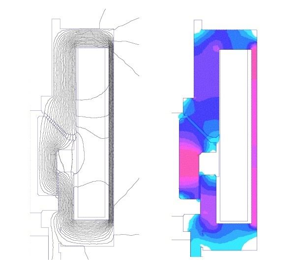
Magnetic circuit
A typical magnetic circuit is driven by a coil winding with controlled current in order to develop a magnetic flux across a working air gap. Out of necessity there is a circular air gap that can only provide radial force (also known as side loading). These two air gaps dominate the magnetic circuit reluctance. The rate of change of the working air gap stored energy provides the axial magnetic force.