
Paradigm concurrent, reactive Typing discipline strong | First appeared 1980s Website IEEE VASG | |
 | ||
VHDL (VHSIC Hardware Description Language) is a hardware description language used in electronic design automation to describe digital and mixed-signal systems such as field-programmable gate arrays and integrated circuits. VHDL can also be used as a general purpose parallel programming language.
Contents
History
VHDL was originally developed at the behest of the U.S Department of Defense in order to document the behavior of the ASICs that supplier companies were including in equipment.
The idea of being able to simulate the ASICs from the information in this documentation was so obviously attractive that logic simulators were developed that could read the VHDL files. The next step was the development of logic synthesis tools that read the VHDL, and output a definition of the physical implementation of the circuit.
Due to the Department of Defense requiring as much of the syntax as possible to be based on Ada, in order to avoid re-inventing concepts that had already been thoroughly tested in the development of Ada, VHDL borrows heavily from the Ada programming language in both concepts and syntax.
The initial version of VHDL, designed to IEEE standard IEEE 1076-1987, included a wide range of data types, including numerical (integer and real), logical (bit and boolean), character and time, plus arrays of bit called bit_vector and of character called string.
A problem not solved by this edition, however, was "multi-valued logic", where a signal's drive strength (none, weak or strong) and unknown values are also considered. This required IEEE standard 1164, which defined the 9-value logic types: scalar std_logic and its vector version std_logic_vector. Being a resolved subtype of its std_Ulogic parent type, std_logic typed signals allow multiple driving for modeling bus structures, whereby the connected resolution function handles conflicting assignments adequately.
The updated IEEE 1076, in 1993, made the syntax more consistent, allowed more flexibility in naming, extended the character type to allow ISO-8859-1 printable characters, added the xnor operator, etc.
Minor changes in the standard (2000 and 2002) added the idea of protected types (similar to the concept of class in C++) and removed some restrictions from port mapping rules.
In addition to IEEE standard 1164, several child standards were introduced to extend functionality of the language. IEEE standard 1076.2 added better handling of real and complex data types. IEEE standard 1076.3 introduced signed and unsigned types to facilitate arithmetical operations on vectors. IEEE standard 1076.1 (known as VHDL-AMS) provided analog and mixed-signal circuit design extensions.
Some other standards support wider use of VHDL, notably VITAL (VHDL Initiative Towards ASIC Libraries) and microwave circuit design extensions.
In June 2006, the VHDL Technical Committee of Accellera (delegated by IEEE to work on the next update of the standard) approved so called Draft 3.0 of VHDL-2006. While maintaining full compatibility with older versions, this proposed standard provides numerous extensions that make writing and managing VHDL code easier. Key changes include incorporation of child standards (1164, 1076.2, 1076.3) into the main 1076 standard, an extended set of operators, more flexible syntax of case and generate statements, incorporation of VHPI (VHDL Procedural Interface) (interface to C/C++ languages) and a subset of PSL (Property Specification Language). These changes should improve quality of synthesizable VHDL code, make testbenches more flexible, and allow wider use of VHDL for system-level descriptions.
In February 2008, Accellera approved VHDL 4.0 also informally known as VHDL 2008, which addressed more than 90 issues discovered during the trial period for version 3.0 and includes enhanced generic types. In 2008, Accellera released VHDL 4.0 to the IEEE for balloting for inclusion in IEEE 1076-2008. The VHDL standard IEEE 1076-2008 was published in January 2009.
Standardization
The IEEE Standard 1076 defines the VHSIC Hardware Description Language or VHDL. It was originally developed under contract F33615-83-C-1003 from the United States Air Force awarded in 1983 to a team with Intermetrics, Inc. as language experts and prime contractor, with Texas Instruments as chip design experts and IBM as computer system design experts. The language has undergone numerous revisions and has a variety of sub-standards associated with it that augment or extend it in important ways.
1076 was and continues to be a milestone in the design of electronic systems.
Revisions
Related standards
Design
VHDL is commonly used to write text models that describe a logic circuit. Such a model is processed by a synthesis program, only if it is part of the logic design. A simulation program is used to test the logic design using simulation models to represent the logic circuits that interface to the design. This collection of simulation models is commonly called a testbench.
A VHDL simulator is typically an event-driven simulator. This means that each transaction is added to an event queue for a specific scheduled time. E.g. if a signal assignment should occur after 1 nanosecond, the event is added to the queue for time +1ns. Zero delay is also allowed, but still needs to be scheduled: for these cases Delta delay is used, which represent an infinitely small time step. The simulation alters between two modes: statement execution, where triggered statements are evaluated, and event processing, where events in the queue are processed.
VHDL has constructs to handle the parallelism inherent in hardware designs, but these constructs (processes) differ in syntax from the parallel constructs in Ada (tasks). Like Ada, VHDL is strongly typed and is not case sensitive. In order to directly represent operations which are common in hardware, there are many features of VHDL which are not found in Ada, such as an extended set of Boolean operators including nand and nor. VHDL also allows arrays to be indexed in either ascending or descending direction; both conventions are used in hardware, whereas in Ada and most programming languages only ascending indexing is available.
VHDL has file input and output capabilities, and can be used as a general-purpose language for text processing, but files are more commonly used by a simulation testbench for stimulus or verification data. There are some VHDL compilers which build executable binaries. In this case, it might be possible to use VHDL to write a testbench to verify the functionality of the design using files on the host computer to define stimuli, to interact with the user, and to compare results with those expected. However, most designers leave this job to the simulator.
It is relatively easy for an inexperienced developer to produce code that simulates successfully but that cannot be synthesized into a real device, or is too large to be practical. One particular pitfall is the accidental production of transparent latches rather than D-type flip-flops as storage elements.
One can design hardware in a VHDL IDE (for FPGA implementation such as Xilinx ISE, Altera Quartus, Synopsys Synplify or Mentor Graphics HDL Designer) to produce the RTL schematic of the desired circuit. After that, the generated schematic can be verified using simulation software which shows the waveforms of inputs and outputs of the circuit after generating the appropriate testbench. To generate an appropriate testbench for a particular circuit or VHDL code, the inputs have to be defined correctly. For example, for clock input, a loop process or an iterative statement is required.
A final point is that when a VHDL model is translated into the "gates and wires" that are mapped onto a programmable logic device such as a CPLD or FPGA, then it is the actual hardware being configured, rather than the VHDL code being "executed" as if on some form of a processor chip.
Advantages
The key advantage of VHDL, when used for systems design, is that it allows the behavior of the required system to be described (modeled) and verified (simulated) before synthesis tools translate the design into real hardware (gates and wires).
Another benefit is that VHDL allows the description of a concurrent system. VHDL is a dataflow language, unlike procedural computing languages such as BASIC, C, and assembly code, which all run sequentially, one instruction at a time.
A VHDL project is multipurpose. Being created once, a calculation block can be used in many other projects. However, many formational and functional block parameters can be tuned (capacity parameters, memory size, element base, block composition and interconnection structure).
A VHDL project is portable. Being created for one element base, a computing device project can be ported on another element base, for example VLSI with various technologies.
Design examples
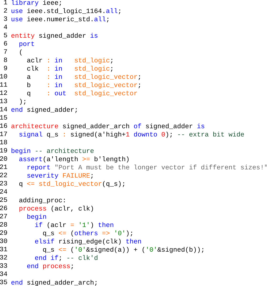
In VHDL, a design consists at a minimum of an entity which describes the interface and an architecture which contains the actual implementation. In addition, most designs import library modules. Some designs also contain multiple architectures and configurations.
A simple AND gate in VHDL would look something like
(Notice that RTL stands for Register transfer level design.) While the example above may seem verbose to HDL beginners, many parts are either optional or need to be written only once. Generally simple functions like this are part of a larger behavioral module, instead of having a separate module for something so simple. In addition, use of elements such as the std_logic type might at first seem to be an overkill. One could easily use the built-in bit type and avoid the library import in the beginning. However, using this 9-valued logic (U,X,0,1,Z,W,H,L,-) instead of simple bits (0,1) offers a very powerful simulation and debugging tool to the designer which currently does not exist in any other HDL.
In the examples that follow, you will see that VHDL code can be written in a very compact form. However, the experienced designers usually avoid these compact forms and use a more verbose coding style for the sake of readability and maintainability. Another advantage to the verbose coding style is the smaller amount of resources used when programming to a Programmable Logic Device such as a CPLD.
Synthesizable constructs and VHDL templates
VHDL is frequently used for two different goals: simulation of electronic designs and synthesis of such designs. Synthesis is a process where a VHDL is compiled and mapped into an implementation technology such as an FPGA or an ASIC. Many FPGA vendors have free (or inexpensive) tools to synthesize VHDL for use with their chips, where ASIC tools are often very expensive.
Not all constructs in VHDL are suitable for synthesis. For example, most constructs that explicitly deal with timing such as wait for 10 ns; are not synthesizable despite being valid for simulation. While different synthesis tools have different capabilities, there exists a common synthesizable subset of VHDL that defines what language constructs and idioms map into common hardware for many synthesis tools. IEEE 1076.6 defines a subset of the language that is considered the official synthesis subset. It is generally considered a "best practice" to write very idiomatic code for synthesis as results can be incorrect or suboptimal for non-standard constructs.
MUX template
The multiplexer, or 'MUX' as it is usually called, is a simple construct very common in hardware design. The example below demonstrates a simple two to one MUX, with inputs A and B, selector S and output X. Note that there are many other ways to express the same MUX in VHDL.
Latch template
A transparent latch is basically one bit of memory which is updated when an enable signal is raised. Again, there are many other ways this can be expressed in VHDL.
D-type flip-flops
The D-type flip-flop samples an incoming signal at the rising (or falling) edge of a clock. This example has an asynchronous, active-high reset, and samples at the rising clock edge.
Another common way to write edge-triggered behavior in VHDL is with the 'event' signal attribute. A single apostrophe has to be written between the signal name and the name of the attribute.
VHDL also lends itself to "one-liners" such as
or
Which can be useful if not all signals (registers) driven by this process should be reset.
Example: a counter
The following example is an up-counter with asynchronous reset, parallel load and configurable width. It demonstrates the use of the 'unsigned' type, type conversions between 'unsigned' and 'std_logic_vector' and VHDL generics. The generics are very close to arguments or templates in other traditional programming languages like C++.
More complex counters may add if/then/else statements within the rising_edge(CLK) elsif to add other functions, such as count enables, stopping or rolling over at some count value, generating output signals like terminal count signals, etc. Care must be taken with the ordering and nesting of such controls if used together, in order to produce the desired priorities and minimize the number of logic levels needed.
Simulation-only constructs
A large subset of VHDL cannot be translated into hardware. This subset is known as the non-synthesizable or the simulation-only subset of VHDL and can only be used for prototyping, simulation and debugging. For example, the following code will generate a clock with a frequency of 50 MHz. It can, for example, be used to drive a clock input in a design during simulation. It is, however, a simulation-only construct and cannot be implemented in hardware. In actual hardware, the clock is generated externally; it can be scaled down internally by user logic or dedicated hardware.
The simulation-only constructs can be used to build complex waveforms in very short time. Such waveform can be used, for example, as test vectors for a complex design or as a prototype of some synthesizer logic that will be implemented in the future.
VHDL simulators
Commercial:
Other: