
 | ||
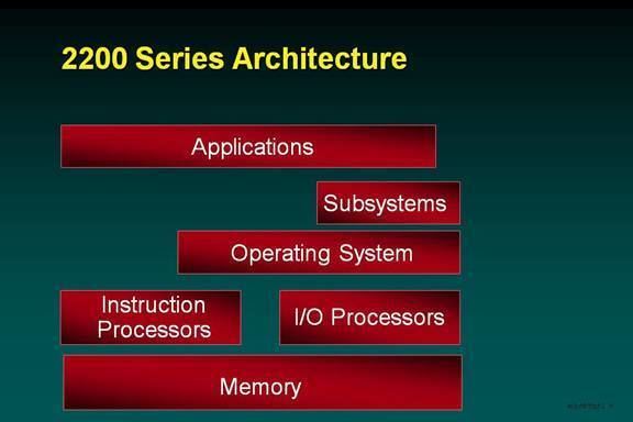
The figure shows a high-level architecture of the OS 2200 system identifying major hardware and software components. The majority of the Unisys software is included in the subsystems and applications area of the model. For example, the database managers are subsystems and the compilers are applications.
Contents
System Basics
The details of the system architecture are covered in Unisys publication 3850 7802 Instruction Processor Programming Reference Manual. Also see UNIVAC 1100/2200 series.
The 1100 Series has used a 36-bit word with 6-bit characters since 1955. This word and character size was a Department of Defense (DoD) requirement. Since the military needed to be able to calculate accurate trajectories, design bridges, and perform other engineering and scientific calculations, they needed more than 32 bits of precision. A 32-bit floating point number only provided about 6 digits of accuracy while a 36 bit number provided the 8 digits of accuracy that were accepted as the minimum requirement. Since memory and storage space and costs drove the system, going to 64 bits was simply not acceptable in general. Almost all computer manufacturers of the time delivered 36-bit systems with 6-bit characters including IBM, DEC, General Electric, and Sylvania.
The 6-bit character set used by the 1100 Series is also a DoD mandated set. It was defined by the Army Signal Corps and called Fieldata (data returned from the field). The 1108 provided a 9-bit character format in order to support ASCII and later the ISO 8-bit sets, but they were not extensively used until the 1980s again because of space constraints.
The 2200 Series architecture provides many registers. Base registers logically contain a virtual address that points to a word in a code or data bank (segment). They may point to the beginning of the bank or to any word within the bank. Index registers are used by instructions to modify the offset of the specified or assumed base register. Simple arithmetic (add, subtract) may be performed on all index registers. In addition, index registers consist of a lower offset portion and an upper increment portion. An instruction may both use the offset value in an index register as part of an address and specify that the increment is to be added to the offset. This allows loops to be accomplished with fewer instructions as incrementing the index by the step size can be accomplished without a separate instruction. Arithmetic registers allow the full set of computational instructions including all floating point operations. Some of those instructions work on adjacent pairs of registers to perform double-precision operations. There are no even-odd constraints. Any two registers may be used as a double-precision value. Four of the arithmetic registers are also index registers (the sets overlap – index register X12 is arithmetic register A0). This allows the full range of calculations to be performed on indexes without having to move the results. The rest of the registers, known as R registers, are used as fast temporary storage and for certain special functions. R1 holds the repeat count for those instructions that may be repeated (block transfer, execute repeated, etc.). R2 holds a bit mask for a few instructions that perform a bitwise logical operation in addition to some other functions (e.g., masked load upper)
There are two full sets of registers (A, X, R, and B). One set, the user registers, is used by all applications and most portions of the operating system. It is saved and restored as part of activity (thread) state. The other set, the Exec registers, is used by interrupt processing routines and some other portions of the operating system that want to avoid having to save and restore user registers. The Exec registers are not writable by user applications although some user code can read them. As a result the Exec is carefully designed never to leave private, secure, or confidential information in registers. Instruction interpretation chooses the appropriate register set to use based on a bit in the Processor State Register. This bit is always set (changed to privileged) on an interrupt. All registers are also visible in the address space, but the Exec portion is protected and a reference by non-privileged code will result in a fault interrupt.
The 2200 Series uses a 36-bit segmented virtual address space. We’ll look later at the addressing architecture.
The 2200 Series is a CISC architecture system. Not only are there a large number of instructions (current count is about 245) but many of them have addressing variants. Some of the variants are encoded directly in the instruction format (partial word references) and some are dependent on Processor State Register settings. Many instructions also perform very complex functions such as one that implements a large part of the COBOL EDIT verb.
The above figure shows some of the building blocks of the architecture. "Data" and "COMM" are two of the primary examples of software subsystems that live in a protection ring between that of a user application and the Exec. There are many other such subsystems and users write their own.
Level
As was mentioned earlier the 2200 Series uses a 36-bit segmented virtual address. The original notion of a segmented space came from the earliest implementation that emphasized code and data separation for performance and the use of shared code banks. Over the years this expanded to provide greater flexibility of levels of sharing and far greater protection for security and reliability. Controlled access to shared data was also introduced.
A virtual address consists of three parts. The high-order 3 bits define the sharing level. This is the heart of the entire addressing and protection scheme. Every thread has eight Bank Descriptor Tables (Segment Descriptor Tables in the industry) based on B16-B23. The tables are indexed by level – level 0 refers to the Bank Descriptor Table (BDT) based on B16, level 2 the BDT based on B18, etc. The level 0 and level 2 BDTs are common to all threads in the system. Every run (process) has its own level 4 BDT, and that BDT is common to all threads in the run. Every user thread has its own unshared level 6 BDT.
Activity
Each extended-mode activity (thread) always has six banks, segments, which are totally unique to it. One is the Return Control Stack which holds information about the calling structure including any security relevant privilege and state changes. It is not accessible by the thread except through the use of the CALL, RETURN, and similar instructions. This is a major part of the protection and reliability mechanism. Applications cannot cause bad effects by changing the return addresses or overwriting the return control stack.
Another unique bank is the automatic storage bank (Activity Local Store stack). This is used by the compilers to hold local variables created within a block. It is also used to hold all parameter lists passed on a call. One of the checks made by the operating system both on its own behalf and when a call is made to a protected subsystem is to ensure that the operands are on the thread-local stack and that the thread has the right to access the memory region referenced by any parameters. Because the parameters are kept in thread-local space, there is no chance that some other thread may change them during or after validation. It is the responsibility of the called procedure to perform similar checks on any secondary parameters that may exist in shared space (i.e., the primary parameter points to a structure that contains pointers). The procedure is expected to copy any such pointers to its own local space before validating them and then to use only that internally held validated pointer.
Activities may create additional segments up to the limit of the available address space (233 words = 8GW or about 36GB). This is a convenient way for multi-threaded applications to get large amounts of memory space knowing that it is totally thread-safe and that they are not taking any space away from the rest of what is available to the program. Each activity in a program has its own independent space meaning an application with say 100 activities is able to use over 800GW (>3TB) of virtual space.
Basic-mode activities do not start out with any such banks as basic-mode programs are not aware of the virtual address space, but any calls to extended-mode subsystems will cause those banks to be created.
Programs
OS 2200 does not implement programs in exactly the same way that UNIX, Linux, and Windows implement processes, but that is the closest analogy. The most obvious difference is that OS 2200 only permits a single program per Run (Job, Session) to be executing at a time. A program may have hundreds of threads, but cannot spawn other programs to run concurrently.
There are several banks at the Program level that contain a mixture of Run (job, session) information and program information. These are control structures for the operating system. They have no access or read-only access for the program. Programs may retrieve information from some of these structures for debugging purposes or to retrieve things like the user-id and terminal-id without the overhead of a system call. They cannot be written by the program. They contain things like the thread state save areas, file control blocks, and accounting information.
The rest of the banks are used by the program. When a program object file is executed, the operating system obtains the bank information from the file and creates banks as needed and loads the bank initial state from the file. The simplest program has a single bank containing code and data. This is considered very bad form, but is permitted for compatibility with old applications. You can only create such an application with assembly language. The standard compilers create one or more code banks and one or more data banks. Normally the code banks are marked as read-only as a debugging and reliability aid. There are no security concerns either way. The program can only affect itself.
Each program thus has its own address space distinct from all other programs in the system. Nothing a program can do can change the contents of any other program’s memory. The OS and shared subsystems are protected by other mechanisms which will be discussed later. Even read access is prohibited to OS and subsystem memory in almost all cases from code in a program. It is possible to create a shared subsystem which is generally readable, or even writable, by multiple programs, but it must be explicitly installed that way by a privileged system administrator. Programs are initially created with just the banks specified in the object file and with a single activity. They may use system calls to create additional banks within their own program level and additional activities.
Subsystems
The closest analogy to a shared subsystem is a .dll. A subsystem is much like a program in many respects except that it does not have any activities associated with it. Instead it is accessed by other programs and subsystems typically via a CALL instruction. In fact, a program is a subsystem plus one or more activities. Every activity belongs to a "home" subsystem which is the program that created it. This subsystem concept is important as an encapsulation of access rights and privilege. Within their home subsystem, activities typically share common access rights to code and data banks. Code banks in the home subsystem are usually read-only, or even execute-only if they contain no constant data, but all activities will have the right to execute them.
Subsystems are also combinations of banks and may contain data banks as well as code banks. All globally shared subsystems must be installed in the system by someone with appropriate administrator privileges. Subsystems may also open files. The Database manager is a subsystem which opens all the database files for its use typically with exclusive access rights. The operating system will attach its own banks to a subsystem to hold the file control tables.
OS
The OS level contains the banks of the Exec. These banks are never directly accessible by either programs or global subsystems. Entry points to the OS are all handled in the same way as a protected subsystem. Calls made to the OS are always via "gates," instructions that exist for that purpose (ER = Executive Request), or via interrupts.
The Bank Descriptor Index (BDI)
The next part of the virtual address is the BDI or Bank Descriptor Index. The Level field selected a particular bank descriptor table base register (B16-B23). Base registers B16-B23 are part of the activity state and are maintained by the Exec with no direct access by the activity. The Bank Descriptor tables for the program and activity levels exist within the program-level banks that belong to the operating system.
The BDI is simply an index into a Bank Descriptor Table. Each entry in the table contains information about a bank. Each such entry describes up to 1MB (256KW) of virtual address space. When a larger contiguous space is needed, consecutive entries are logically combined to create a larger bank up to the maximum of 230 words.
The Bank Descriptor Table Entry (Bank Descriptor – BD) gives the size of the bank (small = up to 256KW, large = up to 16MW, very large = up to 1GW). A small bank is always represented by a single BD. Large banks are represented by up to 64 consecutive BDs and a very large bank by up to 4096 BDs. Large and very large banks need not use all 64 or 4096 consecutive BDs. They only use as many as needed to provide the virtual address space required. The entry also contains upper and lower limits of allowable offsets within the bank. Virtual addresses that are outside the limits generate a fault interrupt. This allows small banks, for example containing a message, to have only the virtual space reserved for it that it actually needs and provides a debugging check against bad pointers and indices.
The BD also contains a key value and access control fields. The fields indicate whether read, write, or execute permission is granted to the instruction processor (3 bits). The Special Access Permissions (SAP) applies only to activities executing within the owning subsystem (really only those with a matching key value). The General Access Permissions (GAP) applies to everyone else and is usually zero (no access). The Exec sets a key value in the state of each activity which may be changed by gate and interrupt transitions.
Protection Mechanisms
The 2200 Series protection architecture uses three pieces of activity state that are reflected in the hardware state. They are Processor Privilege (PP), Ring, and Domain.
Processor Privilege controls the ability to execute privileged instructions and access protected registers and other state. PP=0 is used by the Exec and gives full access to all instructions and privileged state. Exec activities and user activities that have used a gate to access an Exec API run at PP=0.
PP=1 restricts most privileged instructions but does allow reading of the day clocks and reading the contents of some of the privileged registers. None of the privileged registers contain any truly sensitive information, but allowing general read access could easily lead to undetected errors in user programs. Basically at PP=1, instructions that can change the addressing environment, change the clocks, change instrumentation state, or perform I/O are all restricted. PP=1 is rarely used.
PP=2 is the normal user mode and is state in which all other code executes. It is a further restriction of PP=1.
There is also a PP=3 which further restricts the instructions a user program can execute, but it is not currently in use as too many existing programs were using some of those instructions. The intent was to restrict access to instructions that may be system model dependent.
The Domain mechanism is the heart of the protection mechanism. Each BD (bank descriptor) has a lock field consisting of a ring number and domain number. There is also a key field in the state of each activity. If the key matches the lock or the ring in the key is less than the ring in the lock, the activity has Special Access Permission. Otherwise, the activity has General Access Permission.
Ring allows overriding the Domain protection mechanism. User applications run at Ring=3. Protected subsystems run at Ring=2. This gives them access to their own data while still allowing them to access parameters and data in the calling user’s space. Note that it is still not possible for a thread to cause the protected subsystem to access some other user’s space as only this thread’s Bank Descriptor Tables are in use. Ring=0 is used by the OS and allows it to access its own data while still being able to access parameters passed from either user programs or protected subsystems.
Gates are another part of the protection mechanism. A gate is a data structure that controls transitions between domains. A gate lives in a gate bank and the hardware enforces that all references to gates must be to addresses at a proper offset (multiple of a gate size) within a gate bank. A gate contains the target address, new values for PP, Ring, and Domain, and may contain a hidden parameter to be passed to the target. Protected subsystems are not directly accessible to other subsystems. Instead a subsystem must request that a gate be built in its gate bank for access to that subsystem. This permits the operating system to perform any access control checks. The linking system will then find the gate address associated with an entry point. In fact, the whole mechanism is usually transparently handled within the linking system. The hidden parameter permits, for example, a file I/O gate to contain the address or handle of the file control block. Since this is guaranteed to be correct as it was created by the OS when the user opened the file, many error checks can be eliminated from the path length to do I/O.
Instruction Processors
OS 2200 is designed to handle up to 32 instruction processors (or CPUs). A great deal of design has been done over the years optimize for this environment. For example, OS 2200 makes almost no use of critical sections in its design. There’s too high a probability of multiple processors executing the same code. Instead it uses data locking on the finest granularity data possible. Generally locks deal with a single instance of a data object (e.g., activity control structure or file control block) and are contained within the data structure of the object. This minimizes the likelihood of conflicts. When more global locks have to be set as when updating a list of objects, the lock is set only as long as it takes to update the links in the list. Even dispatching is done with separate locks for different priority levels. A check can be made for an empty priority level without setting a lock. The lock need only be set when adding or removing an item from the queue.
The register set is in the visible address space. Registers appear to exist in the first 128 words (2008) of the current instruction bank (B0) when referenced as a data item. This does impose a restriction on compilers to not place any data constants in the first 128 words of a code bank. The result of this is an expansion of the instruction set without requiring additional operation codes. Register-to-register operations are accomplished with the register-storage operation codes.
Typical instructions contain a function code, the target (or source) register, an index register, a base register and a displacement field. When the function code with its qualifier indicates immediate data, the displacement, base, i, and h fields combine to form a single 18-bit immediate value. This allows loading, adding, multiplying, etc. by small constants to eliminate a memory reference and the associated storage.
Processor state as captured on a stack at an interrupt contains the information needed to both return control to the interrupted activity and to determine the type of the interrupt. Interrupts may occur in the middle of long instructions and the state deals with that possibility.
Basic mode is another whole form of instruction formats and addressing. Basic mode provides compatibility with previous systems back to the 1108. For all practical purposes, the hardware architecture defines the rules by which addresses and instructions are converted to the above forms. The most obvious difference in basic mode is the lack of explicit B registers in instructions. Instead there are four implicitly used B registers (B12-B15). There is a complex algorithm using the limits of the banks represented by those B registers, the operand address and the B register within which the current instruction is found.
The most interesting instructions in the 2200 repertoire are the locking and synchronization instructions. Conditional replace is familiar and quite similar to Compare and Swap in the Intel architecture. These instructions always gain exclusive use of the memory/cache-line holding the referenced word. TS and TSS check a bit in the referenced word. If the bit is clear, they set it and continue (TS) or skip (TSS). If the bit is set, they either interrupt (TS) or fall through to the next instruction(TSS). On a TS interrupt the OS takes one of several actions depending on the instruction sequence and activity priority. Real time and Exec activities simply get control back to allow retry unless there is an even higher-priority activity waiting. The presumption is that the lock is set on another processor and will soon be cleared. If it is a user activity not running at real time priority, it may have its priority temporarily reduced and be placed back in the dispatching queues.
Alternatively, the code sequence may indicate that Test & Set Queuing is being used. In this case, the OS places the activity in a wait state and chains it to the end of the list of activities waiting for that particular lock. Activities clearing such a lock check to see if any are waiting and if so notify the OS to allow one of more to try again. Test & Set Queuing is typically used for synchronization within subsystems such as the database manager where activities from many programs may be executing.
The result of these mechanisms is very efficient, low overhead, synchronization among activities.
The queuing architecture is another interesting special case. It was specifically designed to allow very efficient handling of messaging where the number of messages waiting for processing could be almost unlimited. It is also aimed at reducing one of the primary costs of messaging, namely having to constantly move messages around in memory. Even moving them from the communication manager to the message queue subsystem to the processing program is eliminated. Instead each message is placed in a small bank of its own. Instructions allow placing the bank descriptors of these banks in a queue and removing them from a queue. When a message is placed in a queue, the sending program or subsystem no longer has any access to it. That bank is removed from its address space. When a message is retrieved from a queue, the bank becomes part of the receiver's address space. The queuing instructions also provide activity synchronization functions (e.g., wait for a message).
Only "pointers" are moved and they are moved in a way that ensures security and integrity. Once moved, the data in the message is only visible to the recipient.
I/O Processors
All I/O on 2200 Series systems is handled by I/O processors. These processors offload large portions of the I/O path length and recovery, and by fully isolating the main system from I/O faults, interrupts, bus errors, etc. greatly improve reliability and availability. The I/O processors come in three different types (Storage, Communications, Clustering) but the only real difference is the firmware load.
All I/O processors are controlled by the operating system. OS 2200 does provide a raw mode for I/O called "arbitrary device I/O," but even there the OS validates that the program is accessing an allowed device and handles all interrupts and faults before passing appropriate status on to the program. Programs must be granted privileges by the security officer to access devices in arbitrary mode and that may be limited by both the security officer and the system operator to specific devices. Arbitrary I/O is not allowed to a device that is also in use by any other program or the system. The device must be exclusively allocated to the program.
The OS takes very general calls from programs and generates command packets with real memory and device addresses which are then passed to the I/O processor. Firmware in the I/O processor actually creates the device specific (e.g., SCSI) packets, sets up the DMA, issues the I/O, and services the interrupts.