2-ray Ground Reflected Model is a radio propagation model that predicts path loss when the signal received consists of the line of sight component and multi path component formed predominately by a single ground reflected wave.
From the figure the received line of sight component may be written as
r l o s ( t ) = R e { λ G l o s 4 π × s ( t ) e − j 2 π l / λ l } and the ground reflected component may be written as
r g r ( t ) = R e { λ Γ ( θ ) G g r 4 π × s ( t − τ ) e − j 2 π ( x + x ′ ) / λ x + x ′ } where s ( t ) is the transmitted signal, l is the length of the direct line-of-sight (LOS) ray, x + x ′ is the length of the ground-reflected ray, G l o s is the combined antenna gain along the LOS path, G g r is the combined antenna gain along the ground-reflected path, λ is the wavelength of the transmission ( λ = c f , where c is the speed of light and f is the transmission frequency), Γ ( θ ) is ground reflection co-efficient and τ is the delay spread of the model which equals ( x + x ′ − l ) / c
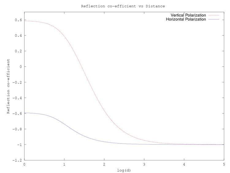
Ground Reflection Γ ( θ ) = sin θ − X sin θ + X
where X for vertical polarization is X v = ε g − cos 2 θ ε g
and for horizontal polarization is X h = ε g − cos 2 θ ,
ε g is the relative permittivity of the ground and θ is the angle between the ground and the reflected ray.
From the figure
x + x ′ = ( h t + h r ) 2 + d 2 and
l = ( h t − h r ) 2 + d 2 ,
therefore, the path difference between them
Δ d = x + x ′ − l = ( h t + h r ) 2 + d 2 − ( h t − h r ) 2 + d 2 and the phase difference between the waves is
Δ ϕ = 2 π Δ d λ The power of the signal received is
( r l o s + r g r ) 2 If the signal is narrow band relative to the delay spread τ , the power equation s ( t ) = s ( t − τ ) may be simplified to
| s ( t ) | 2 ( λ 4 π ) 2 × ( G l o s × e − j 2 π l / λ l + Γ ( θ ) G g r e − j 2 π ( x + x ′ ) / λ x + x ′ ) 2 = P t ( λ 4 π ) 2 × ( G l o s l + Γ ( θ ) G g r e − j Δ ϕ x + x ′ ) 2 where P t is the transmitted power.
When distance between the antennas d is very large relative to the height of the antenna we may expand x + x ′ − l using Generalized Binomial Theorem
x + x ′ − l = ( h t + h r ) 2 + d 2 − ( h t − h r ) 2 + d 2 = d ( ( h t + h r ) 2 d 2 + 1 − ( h t − h r ) 2 d 2 + 1 ) Using the Taylor series of 1 + x :
1 + x = ∑ n = 0 ∞ ( − 1 ) n ( 2 n ) ! ( 1 − 2 n ) ( n ! ) 2 ( 4 n ) x n = 1 + 1 2 x − 1 8 x 2 + 1 16 x 3 − 5 128 x 4 + … , and taking the first two terms
x + x ′ − l ≈ d 2 × ( ( h t + h r ) 2 d 2 − ( h t − h r ) 2 d 2 ) = 2 h t h r d Phase difference may be approximated as
Δ ϕ ≈ 4 π h t h r λ d When d increases asymptotically
d ≈ l ≈ x + x ′ , Γ ( θ ) ≈ − 1 , G l o s ≈ G g r = G ∴ P r = P t ( λ G 4 π d ) 2 × ( 1 − e − j Δ ϕ ) 2 Expanding e − j Δ ϕ using Taylor series
e x = 1 + x 1 1 ! + x 2 2 ! + x 3 3 ! + x 4 4 ! + x 5 5 ! + ⋯ = 1 + x + x 2 2 + x 3 6 + x 4 24 + x 5 120 + ⋯ = ∑ n = 0 ∞ x n n ! and retaining only the first two terms
e − j Δ ϕ ≈ 1 + ( − j Δ ϕ ) + ⋯ = 1 − j Δ ϕ ∴ P r ≈ P t ( λ G 4 π d ) 2 × ( 1 − ( 1 − j Δ ϕ ) ) 2 = P t ( λ G 4 π d ) 2 × ( j Δ ϕ ) 2 = P t ( λ G 4 π d ) 2 × − ( 4 π h t h r λ d ) 2 = − P t G h t 2 h r 2 d 4 Taking the magnitude
| P r | = P t G h t 2 h r 2 d 4 Power varies with inverse fourth power of distance for large d .
In logarithmic units : P r d B m = P t d B m + 10 log 10 ( G h t 2 h r 2 ) − 40 log 10 ( d )
Path loss : P L = P t d B m − P r d B m = 40 log 10 ( d ) − 10 log 10 ( G h t 2 h r 2 )
When d is small compared to transmitter height two waves add constructively to yield higher power and as d increases these waves add up constructively and destructively giving regions of up-fade and down-fade as d increases beyond the critical distance or first Fresnel zone power drops proportional to inverse fourth power of d. An approximation to critical distance may be obtained by setting Δφ to π as critical distance a local maximum.
The standard expression of Log distance path loss model is
P L = P T d B m − P R d B m = P L 0 + 10 γ log 10 d d 0 + X g , The path loss of 2-ray ground reflected wave is
P L = P t d B m − P r d B m = 40 log 10 ( d ) − 10 log 10 ( G h t 2 h r 2 ) where
P L 0 = 40 log 10 ( d 0 ) − 10 log 10 ( G h t 2 h r 2 ) ,
X g = 0 and
γ = 4 for d , d 0 > d c the critical distance.
The 2-ray ground reflected model may be thought as a case of multi-slope model with break point at critical distance with slope 20 dB/decade before critical distance and slope of 40 dB/decade after the critical distance.