
 | ||
In digital communications, a turbo equalizer is a type of receiver used to receive a message corrupted by a communication channel with intersymbol interference (ISI). It approaches the performance of a maximum a posteriori (MAP) receiver via iterative message passing between a soft-in soft-out (SISO) equalizer and a SISO decoder. It is related to turbo codes in that a turbo equalizer may be considered a type of iterative decoder if the channel is viewed as a non-redundant convolutional code. The turbo equalizer is different from classic a turbo-like code, however, in that the 'channel code' adds no redundancy and therefore can only be used to remove non-gaussian noise.
Contents
History
Turbo codes were invented by Claude Berrou in 1990–1991. In 1993, turbo codes were introduced publicly via a paper listing authors Berrou, Glavieux, and Thitimajshima. In 1995 a novel extension of the turbo principle was applied to an equalizer by Douillard, Jézéquel, and Berrou. In particular, they formulated the ISI receiver problem as a turbo code decoding problem, where the channel is thought of as a rate 1 convolutional code and the error correction coding is the second code. In 1997, Glavieux, Laot, and Labat demonstrated that a linear equalizer could be used in a turbo equalizer framework. This discovery made turbo equalization computationally efficient enough to be applied to a wide range of applications.
Standard communication system overview
Before discussing turbo equalizers, it is necessary to understand the basic receiver in the context of a communication system. This is the topic of this section.
At the transmitter, information bits are encoded. Encoding adds redundancy by mapping the information bits
At the receiver, the operations performed by the transmitter are reversed to recover
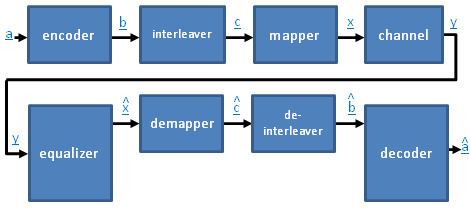
A diagram of the communication system is shown below. In this diagram, the channel is the equivalent baseband channel, meaning that it encompasses the D/A, the up converter, the channel, the down converter, and the A/D.
Turbo equalizer overview
The block diagram of a communication system employing a turbo equalizer is shown below. The turbo equalizer encompasses the equalizer, the decoder, and the blocks in between.
The difference between a turbo equalizer and a standard equalizer is the feedback loop from the decoder to the equalizer. Due to the structure of the code, the decoder not only estimates the information bits
Turbo equalization in practical systems
In practical turbo equalization implementations, an additional issue need to be considered. The channel state information (CSI) that the equalizer operates on comes from some channel estimation technique, and hence un-reliable. Firstly, in order to improve the reliability of the CSI, it is desirable to include the channel estimation block also into the turbo equalization loop, and parse soft or hard decision directed channel estimation within each turbo equalization iteration. Secondly, incorporating the presence of CSI uncertainty into the turbo equalizer design leads to a more robust approach with significant performance gains in practical scenarios.