
 | ||
The Tseytin transformation, alternatively written Tseitin transformation takes as input an arbitrary combinatorial logic circuit and produces a boolean formula in conjunctive normal form (CNF), which can be solved by a CNF-SAT solver. The length of the formula is linear in the size of the circuit. Input vectors that make the circuit output "true" are in 1-to-1 correspondence with assignments that satisfy the formula. This reduces the problem of circuit satisfiability on any circuit (including any formula) to the satisfiability problem on 3-CNF formulas.
Contents
Motivation
The naive approach is to write the circuit as a Boolean expression, and use De Morgan's law and the distributive property to convert it to CNF. However, this can result in an exponential increase in equation size. The Tseytin transformation outputs a formula whose size has grown linearly relative to the input circuit's.
Approach
The output equation is the constant 1 set equal to an expression. This expression is a conjunction of sub-expressions, where the satisfaction of each sub-expression enforces the proper operation of a single gate in the input circuit. The satisfaction of the entire output expression thus enforces that the entire input circuit is operating properly.
For each gate, a new variable representing its output is introduced. A small pre-calculated CNF expression that relates the inputs and outputs is appended (via the "and" operation) to the output expression. Note that inputs to these gates can be either the original literals or the introduced variables representing outputs of sub-gates.
Though the output expression contains more variables than the input, it remains equisatisfiable, meaning that it is satisfiable if, and only if, the original input equation is satisfiable. When a satisfying assignment of variables is found, those assignments for the introduced variables can simply be discarded.
A final clause is appended with a single literal: the final gate's output variable. If this literal is complemented, then the satisfaction of this clause enforces the output expression's to false; otherwise the expression is forced true.
Examples
Consider the following formula
Consider all subformulas (without variables):
Introduce a new variable for each subformula:
Conjunct all substitutions and the substitution for
All substitutions can be transformed into CNF, e.g.
Gate Sub-expressions
Listed is some of the possible sub-expressions that can be created for various logic gates. In an operation expression, C acts as an output; in a CNF sub-expression, C acts as a new Boolean variable. For each operation, the CNF sub-expression is true if and only if C adheres to the contract of the Boolean operation for all possible input values.
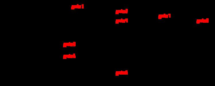
Simple combinatorial logic
The following circuit returns true when at least some of its inputs are true, but not more than two at a time. It implements the equation
Notice that the output of the inverter with
The final output variable is
One possible satisfying assignment of these variables is:
The values of the introduced variables are usually discarded, but they can be used to trace the logic path in the original circuit. Here,
Derivation
Presented is one possible derivation of the CNF sub-expression for some chosen gates:
OR Gate
An OR gate with two inputs A and B and one output C is satisfies the following conditions:
- if the output C is true, then at least one of its inputs A or B is true,
- if the output C is false, then both its inputs A and B are false.
We can express these two conditions as the conjunction of two implications:
Replacing the implications with equivalent expressions involving only conjunctions, disjunctions, and negations yields
which is nearly in conjunctive normal form already. Distributing the rightmost clause twice yields
and applying the associativity of conjunction gives the CNF formula
NOT Gate
The NOT gate is operating properly when its input and output oppose each other. That is:
- if the output C is true, the input A is false
- if the output C is false, the input A is true
express these conditions as an expression that must be satisfied:
NOR Gate
The NOR gate is operating properly when the following conditions hold:
- if the output C is true, then neither A or B are true
- if the output C is false, then at least one of A and B were true
express these conditions as an expression that must be satisfied: