
 | ||
When measuring the value of an alternating current signal it is often necessary to convert the signal into a direct current signal of equivalent value which is known as the root mean square (RMS) value. Most low-cost instrumentation and signal converters carry out this conversion by filtering the signal into an average rectified value and applying a correction factor.
Contents
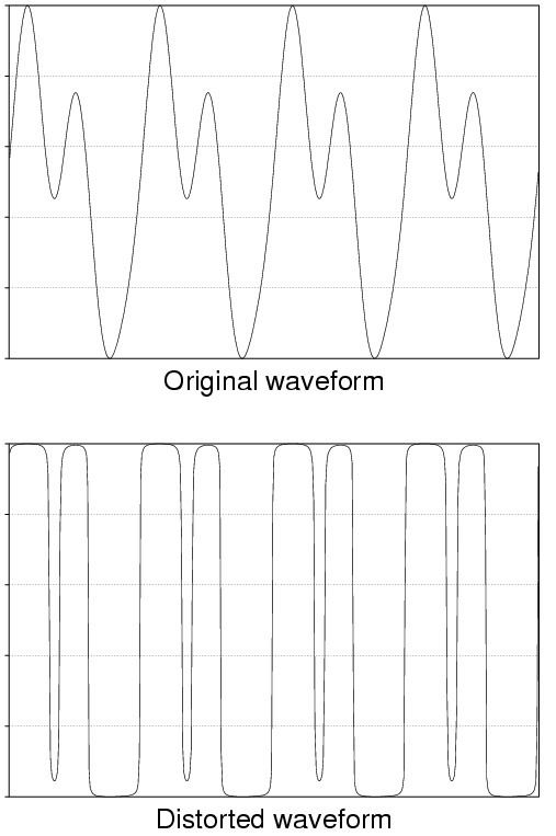
The value of the correction factor applied is only correct if the input signal is sinusoidal. The true RMS value is actually proportional to the square root of the average of the square of the curve, and not to the average of the absolute value of the curve. For any given waveform, the ratio of these two averages is constant and, as most measurements are made on what are (nominally) sine waves, the correction factor assumes this waveform; but any distortion or offsets will lead to errors. Although in most cases this produces adequate results, a correct conversion or the measurement of non-sinusoidal values requires a more complex and costly converter, known as a true RMS converter.
Thermal converters
The RMS value of an alternating current is also known as its heating value, as it is a voltage which is equivalent to the direct current value that would be required to get the same heating effect. For example, if we applied 120 V AC RMS to a resistive heating element it would heat up by exactly the same amount as if we had applied 120V DC.
This principle was exploited in early thermal converters. The AC signal would be applied to a small heating element that was matched with a thermistor, which could be used in a DC measuring circuit.
The technique is not very precise but it will measure any waveform at any frequency (except for extremely low frequencies). A big drawback is that it is low-impedance: that is, the power used to heat the thermistor comes from the circuit being measured. If the circuit being measured can support the heating current, then it is possible to make a post-measurement calculation to correct the effect, as the impedance of the heating element is known. If the signal is small then a pre-amplifier is necessary, and the measuring capabilities of the instrument will be limited by this pre-amplifier. In radio frequency (RF) work, the low impedance is not necessarily a drawback since 50 ohm driving and terminating impedances are widely used.
Thermal converters have become quite rare, but as they are inherently simple and cheap they are still used by radio hams and hobbyists, who may remove the thermal element of an old unreliable instrument and incorporate it into a modern design of their own construction. Additionally, at very high frequencies (microwave), RF power meters still use thermal techniques to convert the RF energy to a voltage. Thermal-based power meters are the norm for millimeter wave (MMW) RF work.
Analog electronic converters
Analog electronic circuits may use:
Unlike thermal converters they are subject to bandwidth limitations which makes them unsuitable for most RF work. The circuitry before time averaging is particularly crucial for high-frequency performance. The slew rate limitation of the operational amplifier used to create the absolute value (especially at low input signal levels) tends to make the second method the poorest at high frequencies, while the FET method can work close to VHF. Specialist techniques are required to produce sufficiently accurate integrated circuits for complex analog calculations, and very often meters equipped with such circuits offer true RMS conversion as an optional extra with a significant price increase.
Digital RMS converters
If a waveform has been digitized, the correct RMS value may be calculated directly. Most digital and PC-based oscilloscopes include a function to give the RMS value of a waveform. The precision and the bandwidth of the conversion is entirely dependent on the analog to digital conversion. In most cases, true RMS measurements are made on repetitive waveforms, and under such conditions digital oscilloscopes (and a few sophisticated sampling multimeters) are able to achieve very high bandwidths as they sample at a fraction of the signal frequency to obtain a stroboscopic effect.