
First production 20th century | ||
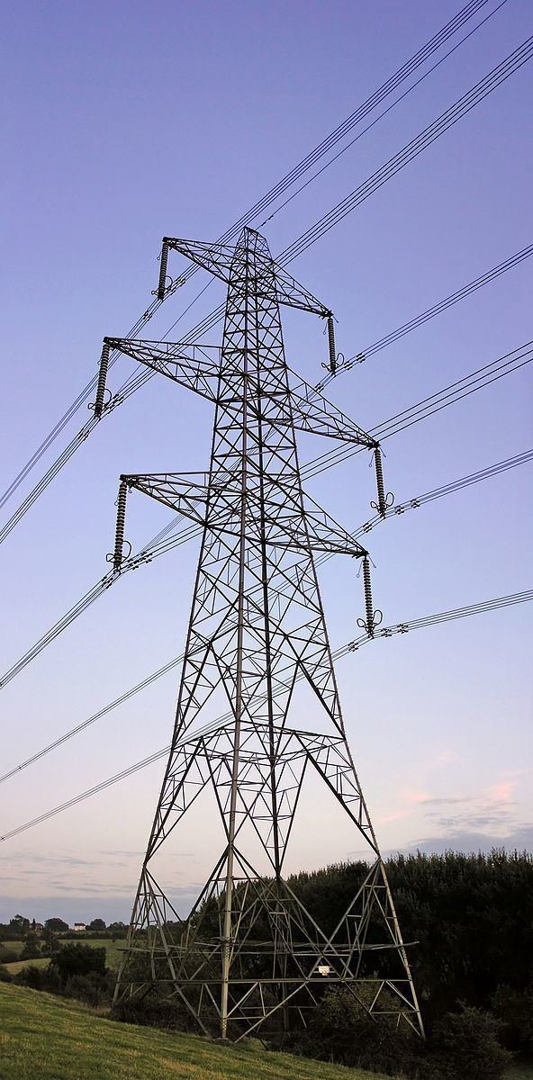 | ||
Type structure, lattice tower and overhead power line | ||
A transmission tower or power tower (electricity pylon in the United Kingdom, Canada and parts of Europe) is a tall structure, usually a steel lattice tower, used to support an overhead power line.
Contents
- Naming
- High voltage AC transmission towers
- High voltage DC transmission towers
- Railway traction line towers
- Towers for different types of currents
- Support structures
- Tubular steel
- Lattice
- Wood
- Concrete
- Special designs
- Assembly
- Markers
- Tower functions
- Cross arms and conductor arrangement
- Notable electricity transmission towers
- References
They are used in high-voltage AC and DC systems, and come in a wide variety of shapes and sizes. Typical height ranges from 15 to 55 m (49 to 180 ft), though the tallest are the 370 m (1,214 ft) towers of a 2,700 m (8,858 ft) span of Zhoushan Island Overhead Powerline Tie. In addition to steel, other materials may be used, including concrete and wood.
There are four major categories of transmission towers: suspension, terminal, tension, and transposition. Some transmission towers combine these basic functions. Transmission towers and their overhead power lines are often considered to be a form of visual pollution. Methods to reduce the visual effect include undergrounding.
Naming
"Transmission tower" is the name for the structure used in the industry in the United States, and some other English-speaking countries. The term "pylon" comes from the basic shape of the structure, an obelisk-like structure which tapers toward the top, and is mostly used in the United Kingdom and parts of Europe in everyday colloquial speech. This term is used infrequently in the United States, as the word "pylon" is commonly used for many other things, mostly for traffic cones.
High voltage AC transmission towers
Three-phase electric power systems are used for high voltage (66- or 69-kV and above) and extra-high voltage (110- or 115-kV and above; most often 138- or 230-kV and above in contemporary systems) AC transmission lines. The towers must be designed to carry three (or multiples of three) conductors. The towers are usually steel lattices or trusses (wooden structures are used in Canada, Germany, and Scandinavia in some cases) and the insulators are either glass or porcelain discs or composite insulators using silicone rubber or EPDM rubber material assembled in strings or long rods whose lengths are dependent on the line voltage and environmental conditions.
Typically, one or two ground wires, also called "guard" wires, are placed on top to intercept lightning and harmlessly divert it to ground.
Towers for high- and extra-high voltage are usually designed to carry two or more electric circuits (with very rare exceptions, only one circuit for 500-kV and higher). If a line is constructed using towers designed to carry several circuits, it is not necessary to install all the circuits at the time of construction. Indeed, for economic reasons, some transmission lines are designed for three (or four) circuits, but only two (or three) circuits are initially installed.
Some high voltage circuits are often erected on the same tower as 110 kV lines. Paralleling circuits of 380 kV, 220 kV and 110 kV-lines on the same towers is common. Sometimes, especially with 110 kV circuits, a parallel circuit carries traction lines for railway electrification.
High voltage DC transmission towers
High-voltage direct current (HVDC) transmission lines are either monopolar or bipolar systems. With bipolar systems a conductor arrangement with one conductor on each side of the tower is used. On some schemes, the ground conductor is used as electrode line or ground return. In this case it had to be installed with insulators equipped with surge arrestors on the pylons in order to prevent electrochemical corrosion of the pylons. For single-pole HVDC transmission with ground return, towers with only one conductor can be used. In many cases, however, the towers are designed for later conversion to a two-pole system. In these cases, often conductors on both sides of the tower are installed for mechanical reasons. Until the second pole is needed, it is either used as electrode line or joined in parallel with the pole in use. In the latter case the line from the converter station to the earthing (grounding) electrode is built as underground cable, as overhead line on a separate right of way or by using the ground conductors.
Electrode line towers are used in some HVDC schemes to carry the power line from the converter station to the grounding electrode. They are similar to structures used for lines with voltages of 10–30 kV, but normally carry only one or two conductors.
Railway traction line towers
Towers used for single-phase AC railway traction lines are similar in construction to those towers used for 110 kV three-phase lines. Steel tube or concrete poles are also often used for these lines. However, railway traction current systems are two-pole AC systems, so traction lines are designed for two conductors (or multiples of two, usually four, eight, or twelve). As a rule, the towers of railway traction lines carry two electric circuits, so they have four conductors. These are usually arranged on one level, whereby each circuit occupies one half of the cross arm. For four traction circuits the arrangement of the conductors is in two-levels and for six electric circuits the arrangement of the conductors is in three levels.
Towers for different types of currents
AC circuits of different frequency and phase-count, or AC and DC circuits, may be installed on the same tower. Usually all circuits of such lines have voltages of 50 kV and more. However, there are some lines of this type for lower voltages, for example, towers used by both railway traction power circuits and the general three-phase AC grid.
Two very short sections of line carry both AC and DC power circuits. One set of such towers is near the terminal of HVDC Volgograd-Donbass on Volga Hydroelectric Power Station. The other are two towers south of Stenkullen, which carry one circuit of HVDC Konti-Skan and üne circuit of the three-phase AC line Stenkullen-Holmbakullen.
Towers carrying AC circuits and DC electrode lines exist in a section of the powerline between Adalph Static Inverter Plant and Brookston the pylons carry the electrode line of HVDC Square Butte.
The electrode line of HVDC CU at the converter station at Coal Creek Station uses on a short section the towers of two AC lines as support.
The overhead section of the electrode line of Pacific DC Intertie from Sylmar Converter Station to the grounding electrode in the Pacific Ocean near Will Rogers State Beach is also installed on AC pylons. It runs from Sylmar East Converter Station to Southern California Edison Malibu Substation, where the overhead line section ends.
In Germany, Austria and Switzerland some transmission towers carry both public AC grid circuits and railway traction power in order to better use rights of way.
Support structures
Towers may be self-supporting and capable of resisting all forces due to conductor loads, unbalanced conductors, wind and ice in any direction. Such towers often have approximately square bases and usually four points of contact with the ground.
A semi-flexible tower is designed so that it can use overhead grounding wires to transfer mechanical load to adjacent structures, if a phase conductor breaks and the structure is subject to unbalanced loads. This type is useful at extra-high voltages, where phase conductors are bundled (two or more wires per phase). It is unlikely for all of them to break at once, barring a catastrophic crash or storm.
A guyed tower has a very small footprint and relies on guy wires in tension to support the structure and any unbalanced tension load from the conductors. A guyed tower can be made in a V shape, which saves weight and cost.
Tubular steel
Poles made of tubular steel generally are assembled at the factory and placed on the right-of-way afterward. Because of its durability and ease of manufacturing and installation, many utilities in recent years prefer the use of monopolar steel or concrete towers over lattice steel for new power lines and tower replacements.
In Germany steel tube pylons are also established predominantly for medium voltage lines, in addition, for high voltage transmission lines or two electric circuits for operating voltages by up to 110 kV. Steel tube pylons are also frequently used for 380 kV lines in France, and for 500 kV lines in the United States.
Lattice
A lattice tower is a framework construction made of steel or aluminium sections. Lattice towers are used for power lines of all voltages, and are the most common type for high-voltage transmission lines. Lattice towers are usually made of galvanized steel. Aluminium is used for reduced weight, such as in mountainous areas where structures are placed by helicopter. Aluminium is also used in environments that would be corrosive to steel. The extra material cost of aluminium towers will be offset by lower installation cost. Design of aluminium lattice towers is similar to that for steel, but must take into account aluminium's lower Young's modulus.
A lattice tower is usually assembled at the location where it is to be erected. This makes very tall towers possible, up to 100 m (328 ft) (and in special cases even higher, as in the Elbe crossing 1 and Elbe crossing 2). Assembly of lattice steel towers can be done using a crane. Lattice steel towers are generally made of angle-profiled steel beams (L- or T-beams). For very tall towers, trusses are often used.
Wood
Wood is a material which is limited in use in high-voltage transmission. Because of the limited height of available trees the maximum height of wooden pylons is limited to approximately 30 m (98 ft). Wood is rarely used for lattice framework; they are instead used to build multi-pole structures, such as H-frame and K-frame structures. The voltages they carry are also limited, such as in other regions, where wood structures only carry voltages up to approximately 30 kV.
In countries such as Canada or United States wooden towers carry voltages up to 345 kV; these can be less costly than steel structures and take advantage of the surge voltage insulating properties of wood. As of 2012, 345 kV lines on wood towers are still in use in the US and some are still being constructed on this technology. Wood can also be used for temporary structures while constructing a permanent replacement.
Concrete
Concrete pylons are used in Germany normally only for lines with operating voltages below 30 kV. In exceptional cases concrete pylons are used also for 110 kV lines, as well as for the public grid or for the railway traction current grid. In Switzerland, concrete pylons with heights of up to 59.5 metres (world's tallest pylon of prefabricated concrete at Littau) are used for 380 kV overhead lines. Concrete poles are also used in Canada and the United States.
Concrete pylons, which are not prefabricated, are also used for constructions taller than 60 metres. One example is a 66 m (217 ft) tall pylon of a 380 kV powerline near Reuter West Power Plant in Berlin. Such pylons look like industrial chimneys. In China some pylons for lines crossing rivers were built of concrete. The tallest of these pylons belong to the Yangtze Powerline crossing at Nanjing with a height of 257 m (843 ft).
Special designs
Sometimes (in particular on steel lattice towers for the highest voltage levels) transmitting plants are installed, and antennas mounted on the top above or below the overhead ground wire. Usually these installations are for mobile phone services or the operating radio of the power supply firm, but occasionally also for other radio services, like directional radio. Thus transmitting antennas for low-power FM radio and television transmitters were already installed on pylons. On the Elbe Crossing 1 tower, there is a radar facility belonging to the Hamburg water and navigation office.
For crossing broad valleys, a large distance between the conductors must be maintained to avoid short-circuits caused by conductor cables colliding during storms. To achieve this, sometimes a separate mast or tower is used for each conductor. For crossing wide rivers and straits with flat coastlines, very tall towers must be built due to the necessity of a large height clearance for navigation. Such towers and the conductors they carry must be equipped with flight safety lamps and reflectors.
Two well-known wide river crossings are the Elbe Crossing 1 and Elbe Crossing 2. The latter has the tallest overhead line masts in Europe, at 227 m (745 ft) tall. In Spain, the overhead line crossing pylons in the Spanish bay of Cádiz have a particularly interesting construction. The main crossing towers are 158 m (518 ft) tall with one crossarm atop a frustum framework construction. The longest overhead line spans are the crossing of the Norwegian Sognefjord (4,597 m (15,082 ft) between two masts) and the Ameralik Span in Greenland (5,376 m (17,638 ft)). In Germany, the overhead line of the EnBW AG crossing of the Eyachtal has the longest span in the country at 1,444 m (4,738 ft).
In order to drop overhead lines into steep, deep valleys, inclined towers are occasionally used. These are utilized at the Hoover Dam, located in the United States, to descend the cliff walls of the Black Canyon of the Colorado. In Switzerland, a NOK pylon inclined around 20 degrees to the vertical is located near Sargans, St. Gallens. Highly sloping masts are used on two 380 kV pylons in Switzerland, the top 32 meters of one of them being bent by 18 degrees to the vertical.
Power station chimneys are sometimes equipped with crossbars for fixing conductors of the outgoing lines. Because of possible problems with corrosion by the flue gases, such constructions are very rare.
A new type of pylon will be used in the Netherlands starting in 2010. The pylons were designed as a minimalist structure by Dutch architects Zwarts and Jansma. The use of physical laws for the design made a reduction of the magnetic field possible. Also, the visual impact on the surrounding landscape is reduced.
A clown-shaped pylon appears in Hungary (GPS coordinates of the location: 47.235548,19.389177).
Assembly
Before transmission towers are even erected, prototype towers are tested at tower testing stations. There are a variety of ways they can then be assembled and erected:
Markers
The International Civil Aviation Organization issues recommendations on markers for towers and the conductors suspended between them. Certain jurisdictions will make these recommendations mandatory, for example that certain power lines must have overhead wire markers placed at intervals, and that warning lights be placed on any sufficiently high towers., this is particularly true of transmission towers which are in close vicinity to airports.
Electricity pylons often have an identification number or code placed on the pole in the form of a sign, an identification plate, painted numbers, or anything else the electric company chooses. These tags are usually marked with the names of the line (either the terminal points of the line or the internal designation of the power company) and the tower number. This makes identifying the location of a fault to the power company that owns the tower easier.
Transmission towers, much like other steel lattice towers including broadcasting or cellphone towers, are marked with signs which discourage public access due to the danger of the high voltage. Often this is accomplished with a sign warning of the high voltage; other times the entire access point to the transmission corridor is marked with a sign. Some countries require that lattice steel towers be equipped with a barbed wire barrier approximately 3 metres (9.8 ft) above ground in order to deter unauthorized climbing. Such barriers can often be found on towers close to roads or other areas with easy public access, even where there is not a legal requirement. In the United Kingdom, all such towers are fitted with barbed wire.
Tower functions
Tower structures can be classified by the way in which they support the line conductors. Suspension structures support the conductor vertically using suspension insulators. Strain structures resist net tension in the conductors and the conductors attach to the structure through strain insulators. Dead-end structures support the full weight of the conductor and also all the tension in it, and also use strain insulators.
Structures are classified as tangent suspension, angle suspension, tangent strain, angle strain, tangent dead-end and angle dead-end. Where the conductors are in a straight line, a tangent tower is used. Angle towers are used where a line must change direction.
Cross arms and conductor arrangement
Generally three conductors are required per AC 3-phase circuit, although single-phase and DC circuits are also carried on towers. Conductors may be arranged in one plane, or by use of several cross-arms may be arranged in a roughly symmetrical, triangulated pattern to balance the impedances of all three phases. If more than one circuit is required to be carried and the width of the line right-of-way does not permit multiple towers to be used, two or three circuits can be carried on the same tower using several levels of cross-arms. Often multiple circuits are the same voltage, but mixed voltages can be found on some structures.
Notable electricity transmission towers
The following electricity transmission towers are notable due to their enormous height, unusual design, unusual construction site or their use in artworks.