
 | ||
A transient recovery voltage (or TRV) for high-voltage circuit breakers is the voltage that appears across the terminals after current interruption. It is a critical parameter for fault interruption by a high-voltage circuit breaker, its characteristics (amplitude, rate of rise) can lead either to a successful current interruption or to a failure (called reignition or restrike).
Contents
The TRV is dependent on the characteristics of the system connected on both terminals of the circuit-breaker, and on the type of fault that this circuit breaker has to interrupt (single, double or three-phase faults, grounded or ungrounded fault ..).
Characteristics of the system include:
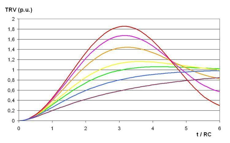
The most severe TRV is applied on the first pole of a circuit-breaker that interrupts current (called the first-pole-to-clear in a three-phase system). The parameters of TRVs are defined in international standards such as IEC and IEEE (or ANSI).
Capacitive load
Typical cases of capacitive loads are unloaded lines and capacitor banks.
Terminal fault
A terminal fault is a fault that occurs at the circuit breaker terminals. The circuit breaker interrupts a short-circuit at current zero, at this instant the supply voltage is maximum and the recovery voltage tends to reach the supply voltage with a high frequency transient. The normalized value of the overshoot or amplitude factor is 1.4.
Short-line-fault
A short-line-fault is a fault that occurs on a line a few hundred meters to several kilometers down the line from the circuit breaker terminal. As shown on Figure 5, the TRV is characterized, in its initial part, by a steep rate-of-rise due to a high-frequency oscillation produced by travelling waves that travel on the line with positive and negative reflections at the circuit breaker terminal and at the fault point, respectively. The superposition of these travelling waves gives the voltage profiles on the line shown on Figures 6 to 14 with, on the horizontal axis, the circuit breaker terminal position on the left and the short-circuit point on the right.
The voltage profile is given at different instants after current interruption, where TL is time needed for a wave to travel from the circuit breaker down the line and back to the circuit breaker terminal.
Figure 15 shows,as function of time, the variation of voltage on the line-side terminal of the circuit breaker. The voltage variation is two times the initial voltage if losses are neglected, in reality it is approximately 1.6 times the initial voltage. The triangular waveshape of voltage on the line-side terminal, combined with a supply-side voltage variation at a lower frequency, produces the sawtooth variation of TRV shown on Figure 5.
A short-line-fault TRV is characterized by a rate-of-rise that is proportional to the slope of current at the time of interruption and therefore to the amplitude of the short-circuit current :
The standardized value of Z is 450 Ω, it is equal to