
 | ||
A torus interconnect is a switch-less network topology for connecting processing nodes in a parallel computer system.
Contents
Introduction
In geometry, a torus is created by revolving a circle about an axis coplanar to the circle. While this is a general definition in geometry, the topological properties of this type of shape describes the network topology in its essence.
Geometry illustration
The following images are 1D, and 2D torus. 1D torus is a simple circle, and 2D torus has the shape of doughnut. The animation below illustrates how a 2D torus is generated from a rectangle by connecting its two pairs of opposite edges. Here the concept of torus is used to describe essentially the beginning and ending of a sequence of nodes are connected, like a doughnut. To better illustrate the concept, and understand what the topology means in network interconnect, we give 3 examples of parallel interconnected nodes using torus topology. At one dimension, a torus topology is equivalent to a ring interconnect network, of a shape of a circle. At 2d, it’s equivalent to a 2D mesh, but with extra connection at the edge nodes, which is the definition of 2D torus.
Torus network topology
We can generalize the rule from the figures above. Torus interconnect is a switch-less topology that can be seen as a mesh interconnect with nodes arranged in a rectilinear array of N = 2, 3, or more dimensions, with processors connected to their nearest neighbors, and corresponding processors on opposite edges of the array connected.[1] In this lattice, each node has 2N connections. This topology got the name from the fact that the lattice formed in this way is topologically homogeneous to an N-dimensional torus.
Visualization
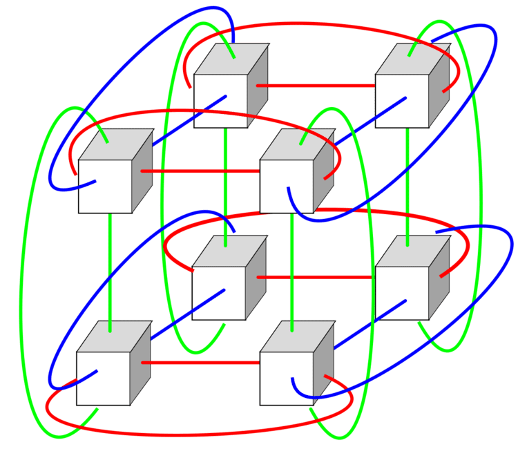
The first 3 dimensions of torus topology network are easier to visualize. Below are the description respectively.
Higher-dimensional arrays are difficult to visualize but we can see from above rule that each higher dimension adds another pair of nearest neighbor connections to each node.
Performance
A number of supercomputers on the TOP500 list use three-dimensional torus networks, e.g. IBM's Blue Gene/L and Blue Gene/P, and the Cray XT3. IBM's Blue Gene/Q uses a five-dimensional torus network. Fujitsu's K computer and the PRIMEHPC FX10 use a proprietary three-dimensional torus 3D mesh interconnect called Tofu.
3D Torus Performance Simulation
Sandeep Palur and Dr. Ioan Raicu from Illinois Institute of Technology conducted experiments to simulate 3D torus performance. Their experiments ran on a computer with 250GB RAM, 48 cores and x86_64 architecture. The simulator they used was ROSS (Rensselaer’s Optimistic Simulation System). They mainly focused on three aspects 1. Varying network size 2. Varying number of servers 3. Varying message size. They concluded that throughput decreases with the increase of servers and network size. Otherwise, throughput increases with the increase of message size.
6D Torus product performance
Fujitsu Limited developed a 6D torus computer model. In their model, 6D torus can achieve 100GB/s off-chip bandwidth, 12 times higher scalability than 3D torus, and high fault tolerance.
Advantages
Because of the connection of opposite edges, data have more options to travel from one node to another which greatly increased speed.
In a 4*4 mesh interconnect, the longest distance between nodes is from upper left corner to lower right corner. Each datum takes 6 hops to travel the longest path. But in a 4*4 Torus interconnect, upper left corner can travel to lower right corner with only 2 hops
Since data tend to travel less hops, the energy consumption tend to be lower.
Disadvantages
The disadvantage of torus is obvious. Extra wires can make routing process in physical design phase harder, if we want to lay out more wires on chip, it is very likely that we need to increase metal layers or decrease density on a chip which is very expensive. Otherwise, the wires that connect opposite edges can be much longer than other wires. This inequality of link lengths can cause lots of problems because of RC delay.
While long wrap-around links may be the easiest way to visualize the connection topology, in practice, restrictions on cable lengths often make long wrap-around links impractical. Instead, directly connected nodes—including nodes that the above visualization places on opposite edges of a grid, connected by a long wrap-around link—are physically placed nearly adjacent to each other in a folded torus network. Every link in the folded torus network is very short—almost as short as the nearest-neighbor links in a simple grid interconnect—and therefore low-latency.