
 | ||
A time-of-flight camera (ToF camera) is a range imaging camera system that resolves distance based on the known speed of light, measuring the time-of-flight of a light signal between the camera and the subject for each point of the image. The time-of-flight camera is a class of scannerless LIDAR, in which the entire scene is captured with each laser or light pulse, as opposed to point-by-point with a laser beam such as in scanning LIDAR systems.
Contents
- Types of devices
- RF modulated light sources with phase detectors
- Range gated imagers
- Direct Time of Flight imagers
- Components
- Principle
- Simplicity
- Efficient distance algorithm
- Speed
- Background light
- Interference
- Multiple reflections
- Automotive applications
- Human machine interfaces and gaming
- Measurement and machine vision
- Robotics
- Earth topography
- Brands
- References
Time-of-flight camera products for civil applications began to emerge around 2000, as the semiconductor processes became fast enough for such devices. The systems cover ranges of a few centimeters up to several kilometers. The distance resolution is about 1 cm. The lateral resolution of time-of-flight cameras is generally low compared to standard 2D video cameras, with most commercially available devices at 320 × 240 pixels or less as of 2011. Compared to 3D laser scanning methods for capturing 3D images, TOF cameras operate very quickly, providing up to 160 images per second.
Types of devices
Several different technologies for time-of-flight cameras have been developed.
RF-modulated light sources with phase detectors
Photonic Mixer Devices (PMD), the Swiss Ranger, and CanestaVision work by modulating the outgoing beam with an RF carrier, then measuring the phase shift of that carrier on the receiver side. This approach has a modular error challenge; ranges are mod the maximum range, which is the RF carrier wavelength. The Swiss Ranger is a compact, short-range device, with ranges of 5 or 10 meters, with 176 x 144 pixels. With phase unwrapping algorithms, the maximum uniqueness range can be increased. The PMD can provide ranges up to 60m. Illumination is pulsed LEDs, rather than a laser. CanestaVision developer Canesta was purchased by Microsoft in 2010. The Kinect2 for Xbox One was based on ToF technology from Canesta.
Range gated imagers
These devices have a built-in shutter in the image sensor that opens and closes at the same rate as the light pulses are sent out. Because part of every returning pulse is blocked by the shutter according to its time of arrival, the amount of light received relates to the distance the pulse has traveled. This principle was invented by Antonio Medina in 1992. The distance can be calculated using the equation, z = R (S2 − S1) / 2(S1 + S2) + R / 2 for an ideal camera. R is the camera range, determined by the round trip of the light pulse, S1 the amount of the light pulse that is received, and S2 the amount of the light pulse that is blocked.
The ZCam by 3DV Systems is a range-gated system. Microsoft purchased 3DV in 2009. Microsoft's second-generation Kinect sensor was developed using knowledge gained from Canesta and 3DV Systems.
Similar principles are used in the ToF camera line developed by the Fraunhofer Institute of Microelectronic Circuits and Systems and TriDiCam. These cameras employ photodetectors with a fast electronic shutter.
The depth resolution of ToF cameras can be improved with ultra-fast gating intensified CCD cameras. These cameras provide gating times down to 200ps and enable ToF setup with sub-millimeter depth resolution.
Range gated imagers can also be used in 2D imaging to suppress anything outside a specified distance range, such as to see through fog. A pulsed laser provides illumination, and an optical gate allows light to reach the imager only during the desired time period.
Direct Time-of-Flight imagers
These devices measure the direct time-of-flight required for a single laser pulse to leave the camera and reflect back onto the focal plane array. Also known as "trigger mode", the 3D images captured using this methodology image complete spatial and temporal data, recording full 3D scenes with single laser pulse. This allows rapid acquisition and rapid real-time processing of scene information. For time-sensitive autonomous operations, this approach has been demonstrated for autonomous space testing and operation such as used on the OSIRIS-REx Bennu asteroid sample and return mission and autonomous helicopter landing.
Advanced Scientific Concepts, Inc. provides application specific (e.g. aerial, automotive, space) Direct TOF vision systems known as 3D Flash LIDAR cameras. Their approach utilizes InGaAs Avalanche Photo Diode (APD) or PIN photodetector arrays capable of imaging laser pulse in the 980 nm to 1600 nm wavelengths.
Components
A time-of-flight camera consists of the following components:
Principle
The simplest version of a time-of-flight camera uses light pulses or a single light pulse. The illumination is switched on for a very short time, the resulting light pulse illuminates the scene and is reflected by the objects in the field of view. The camera lens gathers the reflected light and images it onto the sensor or focal plane array. Depending upon the distance, the incoming light experiences a delay. As light has a speed of approximately c = 300,000,000 meters per second, this delay is very short: an object 2.5 m away will delay the light by:
For amplitude modulated arrays, the pulse width of the illumination determines the maximum range the camera can handle. With a pulse width of e.g. 50 ns, the range is limited to
These short times show that the illumination unit is a critical part of the system. Only with special LEDs or lasers is it possible to generate such short pulses.
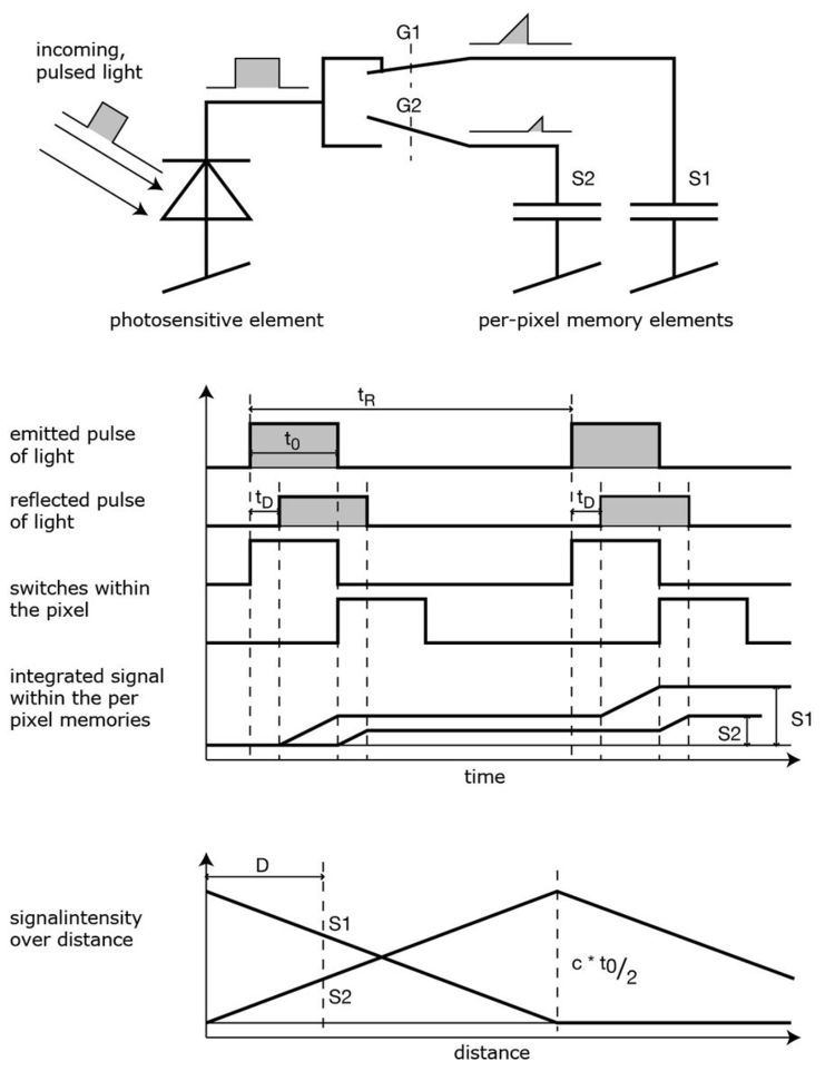
The single pixel consists of a photo sensitive element (e.g. a photo diode). It converts the incoming light into a current. In analog timing imagers, connected to the photo diode are fast switches, which direct the current to one of two (or several) memory elements (e.g. a capacitor) that act as summation elements. In digital timing imagers, a time counter, that can be running at several gigahertz, is connected to each photodetector pixel and stops counting when light is sensed.
In the diagram of an amplitude modulated array analog timer, the pixel uses two switches (G1 and G2) and two memory elements (S1 and S2). The switches are controlled by a pulse with the same length as the light pulse, where the control signal of switch G2 is delayed by exactly the pulse width. Depending on the delay, only part of the light pulse is sampled through G1 in S1, the other part is stored in S2. Depending on the distance, the ratio between S1 and S2 changes as depicted in the drawing. Because only small amounts of light hit the sensor within 50 ns, not only one but several thousand pulses are sent out (repetition rate tR) and gathered, thus increasing the signal to noise ratio.
After the exposure, the pixel is read out and the following stages measure the signals S1 and S2. As the length of the light pulse is defined, the distance can be calculated with the formula:
In the example, the signals have the following values: S1 = 0.66 and S2 = 0.33. The distance is therefore:
In the presence of background light, the memory elements receive an additional part of the signal. This would disturb the distance measurement. To eliminate the background part of the signal, the whole measurement can be performed a second time with the illumination switched off. If the objects are further away than the distance range, the result is also wrong. Here, a second measurement with the control signals delayed by an additional pulse width helps to suppress such objects. Other systems work with a sinusoidally modulated light source instead of the pulse source.
For direct TOF imagers, such as 3D Flash LIDAR, a single short pulse from 5 to 10 ns is emitted by the laser. The T-zero event (the time the pulse leaves the camera) is established by capturing the pulse directly and routing this timing onto the focal plane array. T-zero is used to compare the return time of the returning reflected pulse on the various pixels of the focal plane array. By comparing T-zero and the captured returned pulse and comparing the time difference, each pixel accurately outputs a direct time-of-flight measurement. The round trip of a single pulse for 100 meters is 660 ns. With a 10 ns pulse, the scene is illuminated and the range and intensity captured in less than 1 microsecond.
Simplicity
In contrast to stereo vision or triangulation systems, the whole system is very compact: the illumination is placed just next to the lens, whereas the other systems need a certain minimum base line. In contrast to laser scanning systems, no mechanical moving parts are needed.
Efficient distance algorithm
It is a direct process to extract the distance information out of the output signals of the TOF sensor. As a result, this task uses only a small amount of processing power, again in contrast to stereo vision, where complex correlation algorithms are implemented. After the distance data has been extracted, object detection, for example, is also a straightforward process to carry out because the algorithms are not disturbed by patterns on the object.
Speed
Time-of-flight cameras are able to measure the distances within a complete scene with a singleshot. As the cameras reach up to 160 frames per second, they are ideally suited to be used in real-time applications.
Background light
When using CMOS or other integrating detectors or sensors that use visible or near infra-red light (400 nm - 700 nm), although most of the background light coming from artificial lighting or the sun is suppressed, the pixel still has to provide a high dynamic range. The background light also generates electrons, which have to be stored. For example, the illumination units in many of today's TOF cameras can provide an illumination level of about 1 watt. The Sun has an illumination power of about 50 watts per square meter after the optical band-pass filter. Therefore, if the illuminated scene has a size of 1 square meter, the light from the sun is 50 times stronger than the modulated signal. For non-integrating TOF sensors that do not integrate light over time and are using near-infrared detectors (InGaAs) to capture the short laser pulse, direct viewing of the sun is a non-issue because the image is not integrated over time, rather captured within a short acquisition cycle typically less than 1 microsecond. Such TOF sensors are used in space applications and in consideration for automotive applications.
Interference
In certain types of TOF devices, if several time-of-flight cameras are running at the same time, the TOF cameras may disturb each other's measurements. To be clear, this is not true of all TOF sensors. There exist several possibilities for dealing with this problem:
For Direct TOF type cameras that use a single laser pulse for illumination, because the single laser pulse is short (e.g. 10 nano-seconds), the round trip TOF to and from the objects in the field of view is correspondingly short (e.g. 100 meters = 660 ns TOF round trip), for an imager capturing at 30 Hz, the probability of an interfering interaction is the time that the camera acquisition gate is open divided by the time between laser pulses or approximately 1 in 50,000 (0.66 us divided by 33 ms).
Multiple reflections
In contrast to laser scanning systems where a single point is illuminated, the time-of-flight cameras illuminate a whole scene. For a phase difference device (amplitude modulated array), due to multiple reflections, the light may reach the objects along several paths. Therefore, the measured distance may be greater than the true distance. Direct TOF imagers are vulnerable if the light is reflecting from a specular surface. There are published papers available that outline the strengths and weaknesses of the various TOF devices and approaches.
Automotive applications
Time-of-flight cameras are used in assistance and safety functions for advanced automotive applications such as active pedestrian safety, precrash detection and indoor applications like out-of-position (OOP) detection.
Human-machine interfaces and gaming
As time-of-flight cameras provide distance images in real time, it is easy to track movements of humans. This allows new interactions with consumer devices such as televisions. Another topic is to use this type of cameras to interact with games on video game consoles. The second-generation Kinect sensor which is a standard component of the Xbox One console uses a time-of-flight camera for its range imaging, enabling natural user interfaces and gaming applications using computer vision and gesture recognition techniques. Creative and Intel also provide a similar type of interactive gesture time-of-flight camera for gaming, the Senz3D based on the DepthSense 325 camera of Softkinetic. Infineon and PMD Technologies enable tiny integrated 3D depth cameras for close-range gesture control of consumer devices like all-in-one PCs and laptops.
Measurement and machine vision
Other applications are measurement tasks, e.g. for the fill height in silos. In industrial machine vision, the time-of-flight camera helps to classify and locate objects for use by robots, such as items passing by on a conveyor. Door controls can distinguish easily between animals and humans reaching the door.
Robotics
Another use of these cameras is the field of robotics: Mobile robots can build up a map of their surroundings very quickly, enabling them to avoid obstacles or follow a leading person. As the distance calculation is simple, only little computational power is used.
Earth topography
ToF cameras have been used to obtain digital elevation models of the Earth's surface topography, for studies in geomorphology.