The three point bending flexural test provides values for the modulus of elasticity in bending
E
f
, flexural stress
σ
f
, flexural strain
ϵ
f
and the flexural stress-strain response of the material. The main advantage of a three-point flexural test is the ease of the specimen preparation and testing. However, this method has also some disadvantages: the results of the testing method are sensitive to specimen and loading geometry and strain rate.
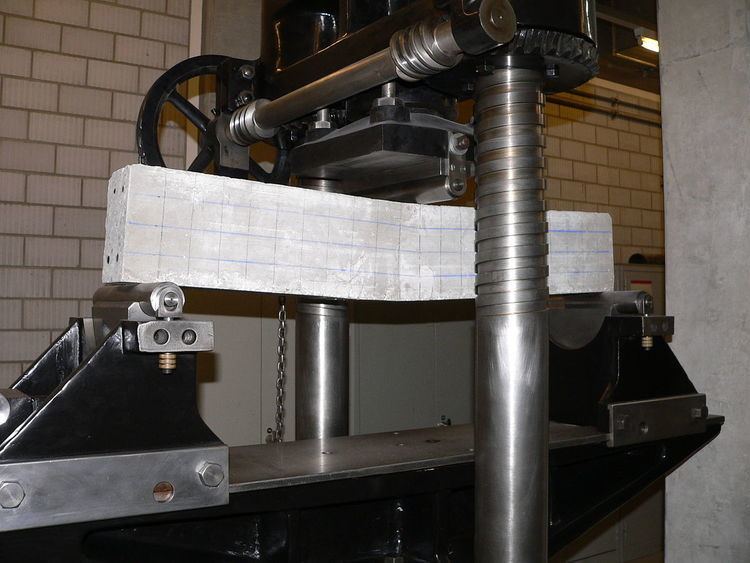
The test method for conducting the test usually involves a specified test fixture on a universal testing machine. Details of the test preparation, conditioning, and conduct affect the test results. The sample is placed on two supporting pins a set distance apart and a third loading pin is lowered from above at a constant rate until sample failure.
Calculation of the flexural stress
σ
f
σ
f
=
3
F
L
2
b
d
2
for a rectangular cross section
σ
f
=
F
L
π
R
3
for a circular cross section
Calculation of the flexural strain
ϵ
f
ϵ
f
=
6
D
d
L
2
Calculation of flexural modulus
E
f
E
f
=
L
3
m
4
b
d
3
in these formulas the following parameters are used:
σ
f
= Stress in outer fibers at midpoint, (MPa)
ϵ
f
= Strain in the outer surface, (mm/mm)
E
f
= flexural Modulus of elasticity,(MPa)
F
= load at a given point on the load deflection curve, (N)
L
= Support span, (mm)
b
= Width of test beam, (mm)
d
= Depth or thickness of tested beam, (mm)
D
= maximum deflection of the center of the beam, (mm)
m
= The gradient (i.e., slope) of the initial straight-line portion of the load deflection
curve,(P/D), (N/mm)
R
= The radius of the beam, (mm)
The fracture toughness of a specimen can also be determined using a three-point flexural test. The stress intensity factor at the crack tip of a single edge notch bending specimen is
K
I
=
4
P
B
π
W
[
1.6
(
a
W
)
1
/
2
−
2.6
(
a
W
)
3
/
2
+
12.3
(
a
W
)
5
/
2
−
21.2
(
a
W
)
7
/
2
+
21.8
(
a
W
)
9
/
2
]
where
P
is the applied load,
B
is the thickness of the specimen,
a
is the crack length, and
W
is the width of the specimen. In a three-point bend test, a fatigue crack is created at the tip of the notch by cyclic loading. The length of the crack is measured. The specimen is then loaded monotonically. A plot of the load versus the crack opening displacement is used to determine the load at which the crack starts growing. This load is substituted into the above formula to find the fracture toughness
K
I
c
.
The ASTM E1290-08 Standard suggests the relation
K
I
=
6
P
B
W
a
1
/
2
Y
where
Y
=
1.99
−
a
/
W
(
1
−
a
/
W
)
(
2.15
−
3.93
a
/
W
+
2.7
(
a
/
W
)
2
)
(
1
+
2
a
/
W
)
(
1
−
a
/
W
)
3
/
2
.
The predicted values of
K
I
are nearly identical for the ASTM and Bower equations for crack lengths less than 0.6
W
.
Standards
ISO 12135: Metallic materials. Unified method for the determination of quasi-static fracture toughness
ISO 12737: Metallic materials. Determination of plane-strain fracture toughness
ASTM D790: Standard test methods for flexural properties of unreinforced and reinforced plastics and electrical insulating materials
ISO 178: Plastics—Determination of flexural properties
ASTM E1290: Standard Test Method for Crack-Tip Opening Displacement (CTOD) Fracture Toughness Measurement.
ASTM D7264: Standard Test Method for Flexural Properties of Polymer Matrix Composite Materials