High power light-emitting diodes (LEDs) can use 350 milliwatts or more in a single LED. Most of the electricity in an LED becomes heat rather than light (about 70% heat and 30% light). If this heat is not removed, the LEDs run at high temperatures, which not only lowers their efficiency, but also makes the LED less reliable. Thus, thermal management of high power LEDs is a crucial area of research and development. It is necessary to limit the junction temperature to a value that will guarantee the desired LED lifetime.
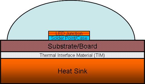
In order to maintain a low junction temperature to keep good performance of an LED, every method of removing heat from LEDs should be considered. Conduction, convection, and radiation are the three means of heat transfer. Typically, LEDs are encapsulated in a transparent resin, which is a poor thermal conductor. Nearly all heat produced is conducted through the back side of the chip. Heat is generated from the PN junction by electrical energy that was not converted to useful light, and conducted to outside ambience through a long path, from junction to solder point, solder point to board, and board to the heat sink and then to the atmosphere. A typical LED side view and its thermal model are shown in the figures.
The junction temperature will be lower if the thermal impedance is smaller and likewise, with a lower ambient temperature. To maximize the useful ambient temperature range for a given power dissipation, the total thermal resistance from junction to ambient must be minimized.
The values for the thermal resistance vary widely depending on the material or component supplier. For example, RJC will range from 2.6 °C/W to 18 °C/W, depending on the LED manufacturer. The thermal interface material’s (TIM) thermal resistance will also vary depending on the type of material selected. Common TIMs are epoxy, thermal grease, pressure-sensitive adhesive and solder. Power LEDs are often mounted on metal-core printed circuit boards (MCPCB), which will be attached to a heat sink. Heat conducted through the MCPCB and heat sink is dissipated by convection and radiation. In the package design, the surface flatness and quality of each component, applied mounting pressure, contact area, the type of interface material and its thickness are all important parameters to thermal resistance design.
Some considerations for passive thermal designs to ensure good thermal management for high power LED operation include:
Adhesive is commonly used to bond LED and board, and board and heat sinks. Using a thermal conductive adhesive can further optimize the thermal performance.
Heat sinks provide a path for heat from the LED source to outside medium. Heat sinks can dissipate power in three ways: conduction (heat transfer from one solid to another), convection (heat transfer from a solid to a moving fluid, for most LED applications the fluid will be air), or radiation (heat transfer from two bodies of different surface temperatures through Thermal radiation).
Material – The thermal conductivity of the material that the heat sink is made from directly affects the dissipation efficiency through conduction. Normally this is aluminum, although copper may be used with an advantage for flat-sheet heat sinks. New materials include thermoplastics that are used when heat dissipation requirements are lower than normal or complex shape would be advantaged by injection molding, and natural graphite solutions which offer better thermal transfer than copper with a lower weight than aluminum plus the ability to be formed into complex two-dimensional shapes. Graphite is considered an exotic cooling solution and does come at a higher production cost. Heat pipes may also be added to aluminum or copper heat sinks to reduce spreading resistance.Shape – Thermal transfer takes place at the surface of the heat sink. Therefore, heat sinks should be designed to have a large surface area. This goal can be reached by using a large number of fine fins or by increasing the size of the heat sink itself.Although a bigger surface area leads to better cooling performance, there must be sufficient space between the fins to generate a considerable temperature difference between the fin and the surrounding air. When the fins stand too close together, the air in between can become almost the same temperature as the fins, so that thermal transmission will not occur. Therefore, more fins do not necessarily lead to better cooling performance.
Surface Finish – Thermal radiation of heat sinks is a function of surface finish, especially at higher temperatures. A painted surface will have a greater emissivity than a bright, unpainted one. The effect is most remarkable with flat-plate heat sinks, where about one-third of the heat is dissipated by radiation. Moreover, a perfectly flat contact area allows the use of a thinner layer of thermal compound, which will reduce the thermal resistance between the heat sink and LED source. On the other hand, anodizing or etching will also decrease the thermal resistance.Mounting method – Heat-sink mountings with screws or springs are often better than regular clips, thermal conductive glue or sticky tape.For heat transfer between LED sources over 15 Watt and LED coolers, it is recommended to use a high thermal conductive interface material (TIM) which will create a thermal resistance over the interface lower than 0.2K/W Currently, the most common solution is to use a phase-change material, which is applied in the form of a solid pad at room temperature, but then changes to a thick, gelatinous fluid once it rises above 45°C.
Heat pipes and vapor chambers
Heat pipes and vapor chambers are passive, and have effective thermal conductivities ranging from 10,000 to 100,000 W/m K. They can provide the following benefits in LED thermal management:
Transport heat to a remote heat sink with minimum temperature dropIsothermalize a natural convection heat sink, increasing its efficiency and reducing its size. In one case, adding five heat pipes reduced the heat sink mass by 34%, from 4.4 kg to 2.9 kg.Efficiently transform the high heat flux directly under an LED to a lower heat flux that can be removed more easily.MCPCB – MCPCB (Metal Core PCB) are those boards which incorporate a base metal material as heat spreader as an integral part of the circuit board. The metal core usually consists of aluminum alloy. Furthermore MCPCB can take advantage of incorporating a dielectric polymer layer with high thermal conductivity for lower thermal resistance.Separation – Separating the LED drive circuitry from the LED board prevents the heat generated by the driver from raising the LED junction temperature.Additive Process – Thick film is a selective additive deposition process which uses material only where it is needed. A more direct connection to the Al heat sink is provided; therefore thermal interface material is not needed for circuit building. Reduces the heat spreading layers and thermal footprint. Processing steps are reduced, along with the number of materials and amount of materials consumed.Insulated Aluminum Materials System – Increases thermal connectivity and provides high dielectric breakdown strength. Materials can be fired at less than 600°C. Circuits are built directly onto aluminum substrates, eliminating the need for thermal interface materials. Through improved thermal connectivity, the junction temperature of the LED can be decreased by up to 10°C. This allows the designer to either decrease the number of LEDs needed on a board, by increasing the power to each LED; or decrease the size of the substrate, to manage dimensional restrictions. It is also proven that decreasing the junction temperature of the LED dramatically improves the LED’s lifetime.Flip chip – The concept is similar to flip-chip in package configuration widely used in the silicon integrated circuit industry. Briefly speaking, the LED die is assembled face down on the sub-mount, which is usually silicon or ceramic, acting as the heat spreader and supporting substrate. The flip-chip joint can be eutectic, high-lead, lead-free solder or gold stub. The primary source of light comes from the back side of the LED chip, and there is usually a built-in reflective layer between the light emitter and the solder joints to reflect up the light which is emitted downward. Several companies have adopted flip-chip packages for their high-power LED, achieving bout 60% reduction in the thermal resistance of the LED while keeping its thermal reliability.