
 | ||
As originally stated in terms of DC resistive circuits only, Thévenin's theorem holds that:
Contents
- Calculating the Thvenin equivalent
- Example
- Conversion to a Norton equivalent
- Practical limitations
- A proof of the theorem
- References
In circuit theory terms, the theorem allows any one-port network to be reduced to a single voltage source and a single impedance.
The theorem also applies to frequency domain AC circuits consisting of reactive and resistive impedances. It means the theorem applies for AC in an exactly same way to DC except that resistances are generalized to impedances.
The theorem was independently derived in 1853 by the German scientist Hermann von Helmholtz and in 1883 by Léon Charles Thévenin (1857–1926), an electrical engineer with France's national Postes et Télégraphes telecommunications organization.
Thévenin's theorem and its dual, Norton's theorem, are widely used to make circuit analysis simpler and to study a circuit's initial-condition and steady-state response. Thévenin's theorem can be used to convert any circuit's sources and impedances to a Thévenin equivalent; use of the theorem may in some cases be more convenient than use of Kirchhoff's circuit laws.
Calculating the Thévenin equivalent
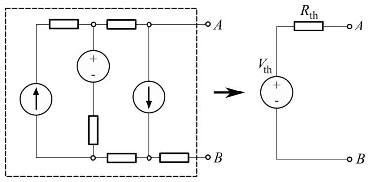
The equivalent circuit is a voltage source with voltage VTh in series with a resistance RTh.
The Thévenin-equivalent voltage VTh is the voltage at the output terminals of the original circuit.It is the open circuited voltage at the output terminals of the original circuit. When calculating a Thévenin-equivalent voltage, the voltage divider principle is often useful, by declaring one terminal to be Vout and the other terminal to be at the ground point.
The Thévenin-equivalent resistance RTh is the resistance measured across points A and B "looking back" into the circuit. It is important to first replace all voltage- and current-sources with their internal resistances. For an ideal voltage source, this means replace the voltage source with a short circuit. For an ideal current source, this means replace the current source with an open circuit. Resistance can then be calculated across the terminals using the formulae for series and parallel circuits. This method is valid only for circuits with independent sources. If there are dependent sources in the circuit, another method must be used such as connecting a test source across A and B and calculating the voltage across or current through the test source.
Note that the replacement of voltage and current sources do the opposite of what the sources themselves are meant to do. A voltage source creates a difference of electric potential between its terminals; its replacement in Thévenin's theorem resistance calculations, a short circuit, equalizes potential. Likewise, a current source's aim is to generate a certain amount of current, whereas an open circuit stops electric flow altogether.
Example
In the example, calculating the equivalent voltage:
(notice that R1 is not taken into consideration, as above calculations are done in an open circuit condition between A and B, therefore no current flows through this part, which means there is no current through R1 and therefore no voltage drop along this part)
Calculating equivalent resistance:
Conversion to a Norton equivalent
A Norton equivalent circuit is related to the Thévenin equivalent by
Practical limitations
A proof of the theorem
The proof involves two steps. First use superposition theorem to construct a solution. Then, use uniqueness theorem to show the solution is unique. The second step is usually implied. First, using the superposition theorem, in general for any linear "black box" circuit which contains voltage sources and resistors, one can always write down its voltage as a linear function of the corresponding current as follows
where the first term reflects the linear summation of contributions from each voltage source, while the second term measures the contribution from all the resistors. The above argument is due to the fact that the voltage of the black box for a given current