
 | ||
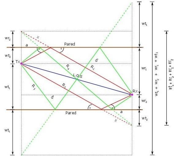
In the theory of antennas, the model of ten rays is designed starting with the geometry of five rays. This models the loss between a transmitting antenna and a receiver. Generally the receiver antenna varies the height with respect to the transmitter antenna. Each ray that reaches the receiver has its respective reflection. The five direct rays are seen from above and the reflected rays are seen laterally, because they are below the direct rays. The first two rays have two reflections, each with each building that separates the street or SW (Only wall reflected); Other two rays strikes twice against the wall (double wall reflected) and finally a ray that going direct to the receiver known as LOS (line of sight).
Contents
Analysis for antennas of heights different located in any point of the street
For the mathematical modeling of the propagation of ten rays, it is taken into consideration a side view and starts modeling the first two rays (line of view and your respect reflection). It is taken into consideration that the antennas have different heights then
The second ray or the reflected ray is done in a similar way to the first ray, but in this case it adds the heights of the antennas for form the right triangle by the reflection of the height of the transmitter.
In the deduction of the third ray it is necessary find the angle between the direct distance
Seeing the model with a side view, it is necessary find a flat distance between the transmitter and the receiver called
Now the height is deducted from the subtraction of the wall with respect to the height of the receiver called
For likeness of triangles it can be deduced the distance since where the ray clashes the wall until the perpendicular of receiver called
The third ray is defined as a model of two rays, by which is:
Since a side view is evidenced the reflected ray that there in
As there are two rays that shock a time on the wall, then the fifth ray is found which is equal to the third ray.
It's equalized the sixth ray with the fourth, because have the same features.
To model the rays that hit on the wall two times is used the Pythagoras’s theorem, because to the direct distance
For the eighth ray is calculated a set of variables that allow deduct the full equation, which is composed for distances and heights that were found by likeness of triangles.
In first instance it taken the flat distance between the wall of the second hit and the receiver:
It is found the distance between the transmitter and the wall in the first hit.
It is found the distance between the height of the wall of the second hit with respect the first hit, getting:
Deducting also the distance between the height of the wall of the second hit with respect the receiver:
Calculating the height of the wall where occurs the first hit:
Calculating the height of the wall where occurs the second hit:
With these settings is calculated the equation for the eighth ray:
For the ninth ray, the equation is the same of the seventh ray due to its features:
For the tenth ray, the equation is the same of the eighth ray because to its form of the reflected ray:
Losses for trajectory on free space
It is considered a transmitted signal through of the space free to a receiver located to a distance d of the transmitter.
Assuming that there are no obstacles between the transmitter and the receiver, the signal it spreads along of a straight line between the two. The model of associated ray with this transmission is called line of sight (LOS), and the signal receiver corresponding is called signal of LOS or ray.
The losses of trajectory of the model of ten rays in the free space, it is defined as: