
Carries Rail traffic Closed 28 December 1879 (1st) Total length 3,264 m Location Dundee, Wormit | Crosses Firth of Tay Construction started 1882 Opened 13 July 1887 Bodies of water River Tay, Firth of Tay | |
 | ||
Locale Dundee to Wormit, Scotland Construction begin 22 July 1871 (1st)
6 July 1883 (2nd) Construction end early 1878 (1st)
1887 (2nd) Architects Thomas Bouch, William Henry Barlow Similar River Tay, Tay Road Bridge, Firth of Tay, Forth Bridge, Law - Dundee | ||
History of sir thomas bouch tay rail bridge dundee
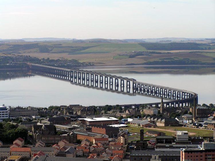
The Tay Bridge carries the main-line railway across the Firth of Tay in Scotland, between the city of Dundee and the suburb of Wormit in Fife. Its span is 2.75 miles (3.5 kilometres).
Contents
- History of sir thomas bouch tay rail bridge dundee
- Tay rail bridge dundee scotland dji phantom 3 pro drone aerial views
- First Tay Bridge
- Design concept
- Design details
- Construction
- Inspection and opening
- Catastrophic failure
- Second bridge
- References
The present structure is the second one on its site.
From about 1854, there had been plans for a Tay crossing, to replace an early train-ferry. The first bridge, opened in 1878, was a single-track lattice design, notable for lightness and low cost. Its sudden collapse in a high wind on 28 December 1879 was one of the great engineering disasters of history, and its causes are still debated today.
The second bridge was a double-track construction of iron and steel, opened in 1887 and still in service. In 2003, a strengthening and refurbishing project was recognised by a major award for the scale and difficulty of the work.
Tay rail bridge dundee scotland dji phantom 3 pro drone aerial views
First Tay Bridge
The original Tay Bridge was designed by noted railway engineer Thomas Bouch, who received a knighthood following the bridge's completion. It was a lattice-grid design, combining cast and wrought iron. The design was well known, having been used first by Kennard in the Crumlin Viaduct in South Wales in 1858, following the innovative use of cast iron in The Crystal Palace. However, the Crystal Palace was not as heavily loaded as a railway bridge. A previous cast iron design, the Dee bridge which collapsed in 1847, failed due to poor use of cast-iron girders. Later, Gustave Eiffel used a similar design to create several large viaducts in the Massif Central (1867).
Proposals for constructing a bridge across the Tay date back to at least 1854. The North British Railway (Tay Bridge) Act received the Royal Assent on 15 July 1870 and the foundation stone was laid on 22 July 1871.
Design concept
The original design was for lattice girders supported by brick piers resting on bedrock shown by trial borings to lie at no great depth under the river. At either end of the bridge the single rail track ran on top of the bridge girder, most of which therefore lay below the pier tops. In the centre section of the bridge (the “high girders”) the railway ran inside the bridge girder, which could then run above the pier tops to give the required clearance to allow passage of sailing ships upriver (e.g. to Perth). To accommodate thermal expansion there were few rigid connections between girders and piers.
As the bridge extended out into the river, it became clear (December 1873) that the bedrock really lay much deeper; too deep to act as a foundation for the bridge piers. Bouch redesigned it quickly to reduce the number of piers and correspondingly increase the span of the girders. The pier foundations were no longer taken down to bedrock; instead they were constructed by sinking brick-lined wrought-iron caissons onto the riverbed, removing sand until the caissons rested upon the consolidated gravel layer which had been misreported as rock, and then filling the caissons with concrete. To reduce the weight the ground under the caissons would have to support, the brick piers were replaced by open lattice iron skeleton piers (each pier had multiple cast-iron columns taking the weight of the bridging girders, with wrought iron horizontal braces and diagonal tiebars linking the columns of the pier to give rigidity and stability). The basic concept was well known, having been used first by Kennard in the Crumlin Viaduct in South Wales in 1858; Bouch had used it for viaducts (notably the Belah Viaduct (1860)) on the South Durham & Lancashire Union Railway line over Stainmore, but for the Tay Bridge, even with the largest practicable caissons the pier dimensions were significantly constrained by the caisson. Bouch’s pier design set 6 columns in a hexagon; this maximised the pier width but not the amount of diagonal bracing directly resisting sideways forces.
Design details
The engineering details on the Tay Bridge were considerably simpler, lighter, and cheaper than on the earlier viaducts. On these the machined base of each column section docked securely into a machined enlarged section of the top of the section below. The joint was then secured by bolts through matching holes on lugs (Crumlin) or flanges (Belah) on the two sections. This 'spigot and faucet' configuration was used (apparently without machining) on some Tay Bridge pier columns, but on some the bolts were relied upon to ensure correct alignment. (In the event, the joints were made using undersized bolts. This gave greater tolerances when assembling the column, but the less positive alignment of the column joints as initially assembled and after any subsequent 'working' of the joint would have weakened the column).
On the Tay Bridge the diagonal bracing was by means of flat bars running from one lug at the column section top (an integral part of the column casting ) to two sling plates bolted to the diagonally opposite lug. Bar and sling plates all had a matching longitudinal slot in them; the tie bar was placed between the sling plates with all three slots aligned and overlapping and a gib driven through all three slots and secured. Two cotters (metal wedges) were then positioned to fill the rest of the slot overlap, and driven in hard to put the tie under tension. Horizontal bracing was provided by (wrought iron) channel iron. The various bolt heads were too close to each other, and to the column for easy tightening up with spanners; this coupled with lack of precision in the preparation of the channel iron braces led to various on site fitting expedients (one of them described by a witness to the enquiry as "about as slovenly a piece of work as ever I saw in my life").)
On the Crumlin and Belah Viaducts, however, horizontal bracing was provided by substantial fitted cast-iron girders securely attached to the columns, with the diagonal braces then being attached to the girders. The Chairman of the Court of Inquiry quoted at length from a contemporary book praising the detailed engineering of the Belah viaduct piers (and describing the viaduct as one of the lightest and cheapest of the kind that had ever been erected).
...It is a distinguishing feature in this viaduct that the cross, or distance girders of the piers encircle the columns, which are turned up at that point, the girders being bored out to fit the turned part with great accuracy. No cement of any kind was used in the whole structure, and the piers when completed, and the vertical and horizontal wrough-iron bracings keyed up, are nearly as rigid as though they were one solid piece...
.... The fitting was all done by machines, which were specially designed for the purpose, and finished the work with mathematical accuracy The flanges of the column were all faced up and their edges turned, and every column was stepped into the one below it with a lip of about 5/8 of an inch in depth, the lip and socket for it being actually turned and bored. That portion of the column against which the cross girders rested was also turned. The whole of these operations were performed at one time, the column being centred in a hollow mandril-lathe. After being turned the columns passed on to a drilling machine, in which all the holes in each flange were drilled out of the solid simultaneously. And as this was done with them all in the same machine, the holes of course, perfectly coincided when the columns were placed one on the other in the progress of erection. Similar care was taken with the cross-girders, which were bored out at the ends by machines designed for that purpose. Thus, when the pieces of the viaduct had to be put together at the place of erection there was literally not a tool required, and neither chipping or filing to retard the progress of the work.
Either, said the Chairman, the Belah viaduct had been over-engineered, or the Tay Bridge had been under engineered.
Construction
Whilst Bouch was revising his design, the company which had the contract for construction went out of business and the contract passed (June 1874) to Hopkin Gilkes and Company, successors to the Middlesbrough company which had made the ironwork for the Belah viaduct. Gilkes originally intended to produce all the bridge ironwork on Teesside, but in the event continued to use a foundry at Wormit to produce the cast-iron components, and to carry out limited post-casting machining operations.
The change in design increased cost and necessitated delay, intensified after two of the high girders fell when being lifted into place during February 1877.
The fallen girders had to be removed and new ones built. and the piers to be erected again ; and this threatened seriously to interfere with the expectation of having the bridge finished for the passage of a train by September. Only eight months were now available for the erection and floating out of six, and the lifting of ten 245’ spans. Five and seven respectively of the 145’ spans had yet to go through the same process. Seven large and three small piers had yet to be built. The weight of iron which had to be put in its place was 2,700 tons, and it seemed incredible that all this could he done in eight months. A good deal would depend on the weather but this was far from favourable.
Despite this, the first engine crossed the bridge on 22 September 1877, and upon its completion in early 1878 the Tay Bridge was the longest in the world. While visiting the city, Ulysses S. Grant commented that it was "a big bridge for a small city".
Inspection and opening
Like all UK rail lines, the Tay Bridge was subject to a Board of Trade inspection before it could carry passenger trains. The inspection was conducted 25–27 February 1878 by Major General Hutchinson of the Railway Inspectorate, who measured the deflection of the 245 ft bridge girders under a distributed load of 1.5 tons per foot (5 t/m) due to heavy locomotives (travelling at up to 40 mph (65 km/hr) as less than 2 inches (50 mm). He reported that "these results are in my opinion to be regarded as satisfactory. The lateral oscillation [roughly, rhythmic side-to-side movement] as observed by the theodolite when the engines ran over at speed, was very slight and the structure overall showed great stiffness". He required some minor remedial work and 'recommended' a 25 mph speed limit over the bridge. (Hutchinson subsequently explained to the Inquiry that he had suggested the speed limit because of the minimal taper on the piers.) The inspection report added '... When again visiting the spot I should wish, if possible, to have an opportunity of observing the effects of high wind when a train of carriages is running over the bridge ...'.
The bridge was opened for passenger traffic on 1 June 1878, formal opening ceremonies having taken place the previous day, in the course of which Thomas Bouch was made a burgess of Dundee "in respect of his meritorious services as engineer of the bridge....". The following year (20 June 1879) Queen Victoria crossed the bridge to return south from Balmoral; Bouch was presented to her before she did so, on 26 June 1879 he was knighted by the Queen at Windsor Castle.
Catastrophic failure
On the night of 28 December 1879 at 7.15 pm, the bridge collapsed after its central spans gave way during high winter gales. A train with six carriages carrying seventy-five passengers and crew, crossing at the time of the collapse, plunged into the icy waters of the Tay. All seventy-five were lost. The disaster stunned the whole country and sent shock waves through the Victorian engineering community. The ensuing enquiry revealed that the bridge did not allow for high winds. At the time a gale estimated at force ten or eleven (Tropical Storm force winds: 55-72 mph/80–117 km/hr) had been blowing down the Tay estuary at right angles to the bridge. The engine itself (North British Railway no. 224) was salvaged from the river and restored to the railways for service. The collapse of the bridge, opened only nineteen months earlier and passed as safe by the Board of Trade, is still the most notorious bridge disaster of the British Isles. The disaster was commemorated in "The Tay Bridge Disaster", one of the best-known verse efforts of William McGonagall. German poet Theodor Fontane within 10 days of the disaster wrote his famous poem Die Brück’ am Tay.
The stumps of the original bridge piers are still visible above the surface of the Tay even at high tide.
Second bridge
A new double-track bridge was designed by William Henry Barlow and built by William Arrol & Co. 18 metres (59 ft) upstream of, and parallel to, the original bridge. The bridge proposal was formally incorporated in July 1881 and the foundation stone laid on 6 July 1883. Construction involved 25,000 metric tons (28,000 short tons) of iron and steel, 70,000 metric tons (77,000 short tons) of concrete, ten million bricks (weighing 37,500 metric tons (41,300 short tons)) and three million rivets. Fourteen men lost their lives during its construction, most by drowning.
The second bridge opened on 20 June 1887 and remains in use. In 2003, a £20.85 million strengthening and refurbishment project on the bridge won the British Construction Industry Civil Engineering Award, in consideration of the staggering scale and logistics involved. More than 1,000 metric tons (1,100 short tons) of bird droppings were scraped off the ironwork lattice of the bridge using hand tools, and bagged into 25-kilogram (55 lb) sacks. Hundreds of thousands of rivets were removed and replaced, all work being done in very exposed conditions high over a firth with fast-running tides.
Double-heading of locomotives is prohibited across the bridge; consecutive locomotives must be separated by at least 60 feet (18 m) using barrier or reach wagons.