
 | ||
The Tilted Terminated Folded Dipole (T2FD or TTFD) or Balanced Termination, Folded Dipole (BTFD) - also known as W3HH antenna - is a general-purpose shortwave antenna developed in the late 1940s by the United States Navy. It performs reasonably well over a broad frequency range, without marked dead spots in terms of either frequency, direction, or angle of radiation above the horizon.
Contents
Although inferior in electrical terms (up to 30% of the RF power is converted to heat in the resistor ) to antennas specifically designed for given frequency bands, or optimized for directionality, its all-around performance, relatively modest size, low cost, and the fact that it does not require any complex electronic matching to operate with a standard shortwave transmitter, have made it popular in professional shortwave communications.
History
The history of the TTFD antenna divides conveniently into three different phases: It was first developed for use as a general purpose antenna on Naval ships in the 1940s. The design became public in the 1950s and was adopted by radio amateurs, but then fell out of use with the advent of shorter wavelengths and the widespread adoption of low-impedance transmitters and antenna feeds. Recently, with the advent of multiple new frequency bands which are not even-integer multiples of existing bands’ frequencies, it has started to draw renewed attention from radio amateurs.
Origin
The TTFD antenna was originally developed during WW II at the San Diego naval base for use on ships, where antenna size is limited, but where the radio-frequency ground-plane is spectacularly efficient. The design properties of the antenna make it ideal for use in small spaces at long wavelengths, where the antenna cannot be conveniently aimed in any particular direction, and where the number of antennas is limited, compared to the number of operating frequencies.
Early amateur use
One of the developers of the original Navy antenna, Captain Gil L. Countryman, was also an amateur radio enthusiast (W3HH). He introduced the design to other amateurs at the beginning of the 1950s. It was a popular antenna design during the middle of the 20th century, but fell out of common use during the latter part of the century with the growing popularity of shorter wavelengths, which only required dipole antennas of 16 feet or less. Also contributing to its falling popularity was the growing fad for low-impedance antenna feeds.
Recent revival
Since the late 1980s, amateur radio operators and hobby shortwave listeners have ‘rediscovered’ this antenna, especially for broadcast receiving and for amateur two-way modes such as Morse code and PSK31 where brute force performance is not as important as a 'steady' signal. There have also been (disputed) claims that this antenna is comparatively insensitive to man-made radio interference, making it useful in urban environments, where a low noise floor is often more beneficial than high received signal strength. The T2FD is useful for hidden indoor systems, or where several optimised frequency-specific antennas cannot be accommodated. For example: an indoor antenna only 24 feet long will allow operation on all amateur HF bands above 14 MHz on transmit, and down to 7 MHz on receive.
Construction
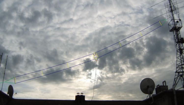
A typical T2FD is built as follows, out of two parallel-wire conductors:
The commercially available B&W AC3-30 antenna varies from the above to cover 3 to 30 MHz with a 90 foot length with an 18-inch spacing of the wires. The balun is a 16:1 ratio, thereby transforming the 50 ohm coax to an 800 Ω feed at the antenna. The resistor load is also 800 Ohms, non-inductive. This allows the antenna impedance to swing from 400 to 1600 Ω over the frequency range intended and thus keep the SWR at the transmitter 2:1 or lower.
Applications and drawbacks
An antenna such as the one described above is usable for both local and medium-long distance communication across a frequency range of about 1:6. For example, an antenna for the lower portion of shortwave (say, 3–18 MHz) will be roughly 33 m (110 feet) long, with conductors spaced 1 m (3.3 feet). For the higher portion of shortwave (5–30 MHz), this antenna will be roughly 20 m (66 feet) long, with a spacing of 60 cm (24 inches). If such long spans cannot be accommodated, smaller antennas will still give adequate receive-only performance down to about half of their lowest design frequency.
Transmit performance, however, degrades rapidly below a certain point. Tests done by Dr.John Belrose showed that though its length is close to a full-size 80 meter (3.5–4.0 MHz) antenna, the T2FD starts to suffer serious signal loss both on transmit and receive below 10 MHz (30 m), with the 80 meter band signals −10 db down from reference at 10 MHz.
As a broadband antenna, the T2FD will normally display a reasonably low standing wave ratio (SWR) across its entire frequency range. However, at some frequencies the loading element may be moderately reactive, so the use of an antenna tuner may be needed when using modern solid-state transmitters at anything approaching their rated power output. Also, “low SWR” does not mean high antenna efficiency. This antenna is not recommended for those wanting to make serious weak signal contacts. A dipole cut for the lowest used frequency, fed with ladder line, and matched with an antenna tuner would perform better than the T2FD over the HF region of frequencies.
Many ready-made commercial versions of the T2FD are available for the professional, military, amateur radio, and hobby listening markets.