
 | ||
Synchrotron radiation is the electromagnetic radiation emitted when charged particles are accelerated radially, i.e., when they are subject to an acceleration perpendicular to their velocity (a ⊥ v). It is produced, for example, in synchrotrons using bending magnets, undulators and/or wigglers. If the particle is non-relativistic, then the emission is called cyclotron emission. If, on the other hand, the particles are relativistic, sometimes referred to as ultrarelativistic, the emission is called synchrotron emission. Synchrotron radiation may be achieved artificially in synchrotrons or storage rings, or naturally by fast electrons moving through magnetic fields. The radiation produced in this way has a characteristic polarization and the frequencies generated can range over the entire electromagnetic spectrum which is also called continuum radiation.
Contents
- History
- Properties of synchrotron radiation
- Emission mechanism
- Synchrotron radiation from accelerators
- Synchrotron radiation in astronomy
- History of detection
- Pulsar wind nebulae
- LinardWiechert Field
- Velocity acceleration synchrotron radiation
- Radiation integral
- Integrating
- Frequency distribution of radiated energy
- Synchrotron radiation emission as a function of the beam energy
- Polarization of synchrotron radiation
- Solution of equation of motion and undulator equation
- Radiation from the undulator
- References
History
Syncradiation was named after its discovery in Schenectady, New York from a General Electric synchrotron accelerator built in 1946 and announced in May 1947 by Frank Elder, Anatole Gurewitsch, Robert Langmuir and Herb Pollock in a letter entitled "Radiation from Electrons in a Synchrotron". Pollock recounts:
On April 24, Langmuir and I were running the machine and as usual were trying to push the electron gun and its associated pulse transformer to the limit. Some intermittent sparking had occurred and we asked the technician to observe with a mirror around the protective concrete wall. He immediately signaled to turn off the synchrotron as "he saw an arc in the tube." The vacuum was still excellent, so Langmuir and I came to the end of the wall and observed. At first we thought it might be due to Cherenkov radiation, but it soon became clearer that we were seeing Ivanenko and Pomeranchuk radiation.
Properties of synchrotron radiation
- Broad Spectrum (which covers from microwaves to hard X-rays): the users can select the wavelength required for their experiment;
- High Flux: high intensity photon beam allows rapid experiments or use of weakly scattering crystals;
- High Brilliance: highly collimated photon beam generated by a small divergence and small size source (spatial coherence);
- High Stability: submicron source stability;
- Polarization: both linear and circular;
- Pulsed Time Structure: pulsed length down to tens of picoseconds allows the resolution of process on the same time scale.
Emission mechanism
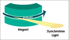
When high-energy particles are in acceleration, including electrons forced to travel in a curved path by a magnetic field, synchrotron radiation is produced. This is similar to a radio antenna, but with the difference that, in theory, the relativistic speed will change the observed frequency due to the Doppler effect by the Lorentz factor, γ. Relativistic length contraction then bumps the frequency observed in the lab by another factor of γ, thus multiplying the GHz frequency of the resonant cavity that accelerates the electrons into the X-ray range. The radiated power is given by the relativistic Larmor formula while the force on the emitting electron is given by the Abraham–Lorentz–Dirac force. The radiation pattern can be distorted from an isotropic dipole pattern into an extremely forward-pointing cone of radiation. Synchrotron radiation is the brightest artificial source of X-rays. The planar acceleration geometry appears to make the radiation linearly polarized when observed in the orbital plane, and circularly polarized when observed at a small angle to that plane. Amplitude and frequency are however focused to the polar ecliptic.
Synchrotron radiation from accelerators
Synchrotron radiation may occur in accelerators either as a nuisance, causing undesired energy loss in particle physics contexts, or as a deliberately produced radiation source for numerous laboratory applications. Electrons are accelerated to high speeds in several stages to achieve a final energy that is typically in the GeV range. In the LHC proton bunches also produce the radiation at increasing amplitude and frequency as they accelerate with respect to the vacuum field, propagating photoelectrons, which in turn propagate secondary electrons from the pipe walls with increasing frequency and density up to 7×10¹⁰. Each proton may lose 6.7 keV per turn due to this phenomenon.
Synchrotron radiation in astronomy
Synchrotron radiation is also generated by astronomical objects, typically where relativistic electrons spiral (and hence change velocity) through magnetic fields. Two of its characteristics include non-thermal power-law spectra, and polarization.
History of detection
It was first detected in a jet emitted by Messier 87 in 1956 by Geoffrey R. Burbidge, who saw it as confirmation of a prediction by Iosif S. Shklovsky in 1953, but it had been predicted earlier by Hannes Alfvén and Nicolai Herlofson in 1950. Solar flares accelerate particles that emit in this way, as suggested by R. Giovanelli in 1948 and described critically by J.H. Piddington in 1952.
T. K. Breus noted that questions of priority on the history of astrophysical synchrotron radiation is complicated, writing:
In particular, the Russian physicist V.L. Ginzburg broke his relationships with I.S. Shklovsky and did not speak with him for 18 years. In the West, Thomas Gold and Sir Fred Hoyle were in dispute with H. Alfven and N. Herlofson, while K.O. Kiepenheuer and G. Hutchinson were ignored by them.
Supermassive black holes have been suggested for producing synchrotron radiation, by ejection of jets produced by gravitationally accelerating ions through the super contorted 'tubular' polar areas of magnetic fields. Such jets, the nearest being in Messier 87, have been confirmed by the Hubble telescope as apparently superluminal, travelling at 6 × c (six times the speed of light) from our planetary frame. This phenomenon is caused because the jets are travelling very near the speed of light and at a very small angle towards the observer. Because at every point of their path the high-velocity jets are emitting light, the light they emit does not approach the observer much more quickly than the jet itself. Light emitted over hundreds of years of travel thus arrives at the observer over a much smaller time period (ten or twenty years) giving the illusion of faster than light travel. There is no violation of special relativity.
Pulsar wind nebulae
A class of astronomical sources where synchrotron emission is important is the pulsar wind nebulae, a.k.a. plerions, of which the Crab nebula and its associated pulsar are archetypal. Pulsed emission gamma-ray radiation from the Crab has recently been observed up to ≥25 GeV, probably due to synchrotron emission by electrons trapped in the strong magnetic field around the pulsar. Polarization in the Crab at energies from 0.1 to 1.0 MeV illustrates a typical synchrotron radiation.
Liénard–Wiechert Field
We start with the expressions for the Liénard–Wiechert field:
where R(t′) = r − r0(t′), R(t′) = |R(t′)|, and n̂(t′) = R(t′)/R(t′), which is the unit vector between the observation point and the position of the charge at the retarded time, and t′ is the retarded time.
In equation (1), and (2), the first terms fall off as the inverse square of the distance from the particle, and this first term is called the generalized Coulomb field or velocity field. And the second terms fall off as the inverse first power of the distance from the source, and it is called the radiation field or acceleration field.
If we ignore the velocity field, the radial component of Poynting's Vector resulted from the Liénard–Wiechert field can be calculated to be
Note that
The energy radiated into per solid angle during a finite period of acceleration from t′ = T1 to t′ = T2 is
Integrating Eq. (4) over the all solid angles, we get relativistic generalization of Larmor's formula
However, this also can be derived by relativistic transformation of the 4-acceleration in Larmor's formula.
Velocity ⊥ acceleration: synchrotron radiation
When the charge is in instantaneous circular motion, its acceleration .→β is perpendicular to its velocity β→. Choosing a coordinate system such that instantaneously β→ is in the z direction and .→β is in the x direction, with the polar and azimuth angles θ and φ defining the direction of observation, the general formula Eq. (4) reduces to
In the relativistic limit
The factors (1 − βcosθ) in the denominators tip the angular distribution forward into a narrow cone like the beam of a headlight pointing ahead of the particle. A plot of the angular distribution (dP/dΩ vs. γθ) shows a sharp peak around θ = 0.
Integration over the whole solid angle yields the total power radiated by one electron
where E is the electron energy, B is the magnetic field, and ρ is the radius of curvature of the track in the field. Note that the radiated power is proportional to 1/m4, 1/ρ2, and B2. In some cases the surfaces of vacuum chambers hit by synchrotron radiation have to be cooled because of the high power of the radiation.
Using
where α is the angle between the velocity and the magnetic field and r is the radius of the circular acceleration, the power emitted is:
Thus the power emitted scales as energy to the fourth, and decreases with the square of the radius and the fourth power of particle mass. This radiation is what limits the energy of an electron-positron circular collider. Generally, proton-proton colliders are instead limited by the maximum magnetic field; this is why, for example, the LHC has a center-of-mass energy 70 times higher than the LEP even though the proton mass is 2000 times the electron mass.
Radiation integral
The energy received by an observer (per unit solid angle at the source) is
Using the Fourier transformation we move to the frequency space
Angular and frequency distribution of the energy received by an observer (consider only the radiation field)
Therefore, if we know the particle's motion, cross products term, and phase factor, we could calculate the radiation integral. However, calculations are generally quite lengthy (even for simple cases as for the radiation emitted by an electron in a bending magnet, they require Airy function or the modified Bessel functions).
Integrating
Trajectory of the arc of circumference is
In the limit of small angles we compute
Substituting into the radiation integral and introducing
where the function K is a modified Bessel function of the second kind.
Frequency distribution of radiated energy
From Eq.(10), we observe that the radiation intensity is negligible for
and critical angle is defined as the angle for which
For frequencies much larger than the critical frequency and angles much larger than the critical angle, the synchrotron radiation emission is negligible.
Integrating on all angles, we get the frequency distribution of the energy radiated.
If we define
where y = ω/ωc. Then
Note that
The formula for spectral distribution of synchrotron radiation, given above, can be expressed in terms of a rapidly converging integral with no special functions involved (see also modified Bessel functions ) by means of the relation:
Synchrotron radiation emission as a function of the beam energy
First, define the critical photon energy as
Then, the relationship between radiated power and photon energy is shown in the graph on the right side. The higher the critical energy, the more photons with high energies are generated. Note that, there is no dependence on the energy at longer wavelength.
Polarization of synchrotron radiation
In Eq.(10), the first term
In the orbit plane
Integrating on all the angles, we find that seven times as much energy is radiated with parallel polarization as with perpendicular polarization. The radiation from a relativistically moving charge is very strongly, but not completely, polarized in the plane of motion.
Solution of equation of motion and undulator equation
An undulator consists of a periodic array of magnets, so that they provide a sinusoidal magnetic field.
Solution of equation of motion is
where
and
and the parameter
Condition for the constructive interference of radiation emitted at different poles is
Expanding
For
This equation is called the undulator equation.
Radiation from the undulator
Radiation integral is
Using the periodicity of the trajectory, we can split the radiation integral into a sum over
where
, and
The radiation integral in an undulator can be written as
where
and Fn depends on the angles of observations and K
On the axis (θ = 0, φ = 0), the radiation integral becomes
and
where
Note that only odd harmonics are radiated on-axis, and as K increases higher harmonic becomes stronger.