
 | ||
In AC electrical power systems, a synchroscope is a device that indicates the degree to which two systems (generators or power networks) are synchronized with each other.
Contents
For two electrical systems to be synchronized, both systems must operate at the same frequency, and the phase angle between the systems must be zero (and two polyphase systems must have the same phase sequence). Synchroscopes measure and display the frequency difference and phase angle between two power systems. Only when these two quantities are zero is it safe to connect the two systems together. Connecting two unsynchronized AC power systems together is likely to cause high currents to flow, which will severely damage any equipment not protected by fuses or circuit breakers.
Operating principles
The simplest aid to synchronizing a generator to another system uses lamps wired between similar phases of the two systems; when the lamps stay dark, the voltage and frequency of the two systems are the same and the generator may be connected. However, the accuracy of this approach is low since it is difficult to discern slight phase differences, and the lamps do not show the relative speeds of the two systems. Synchroscopes are instruments that show the relative frequency (speed) difference and the phase angle between the machine to be synchronized and the system voltage.
Since most synchroscopes are connected only to a single phase of the two systems, they cannot assure that the phase sequence is correct. When generators are newly connected to a power system, or temporary connections are used, other means are required to assure both systems have the same phase sequence.
Synchroscopes are electrodynamic instruments, which rely on the interaction of magnetic fields to rotate a pointer. In most types, unlike voltmeters and wattmeters, there is no restoring spring torque for the magnetically produced torques to overcome; the pointer system is free to rotate continually. Synchroscopes have a damping vane to smooth out vibration of the moving system.
A polarized-vane synchroscope has a field winding with a phase-shifting network arranged to produce a rotating magnetic field. The field windings are connected to the "incoming" machine. A single-phase polarizing winding is connected to the "running" system. It is mounted perpendicular to the field winding and produces a magnetic flux that passes through the moving vanes. The moving vanes turn a shaft that carries a pointer moving over a scale. If the frequency of the source connected to the polarizing winding is different from the source connected to the field winding, the pointer rotates continually at a speed proportional to the difference in system frequencies (the beat frequency). The scale is marked to show the direction of rotation corresponding to the "incoming" machine running faster than the "running" system. When the frequencies match, the moving vanes will rotate to a position corresponding to the phase difference between the two sources. The incoming machine can then be adjusted in speed so that the two systems are in phase agreement.
In the moving iron instrument, an iron vane is mounted on a shaft along with the pointer. The field winding is a three-phase winding, with the phases connected to both the running and incoming sources through a phase-shifting "impedor" network containing resistors, capacitors, and inductors. In this instrument, conceptually the field winding produces two rotating magnetic fields due to the running and incoming sources. The iron vane moves in response to the resultant sum of the two fields.
The cross-coil synchroscope somewhat resembles a wound-field induction motor. A two-phase rotor winding is connected to the incoming machine source by a phase-shifting network through brushes and slip rings. The stationary field winding is connected to the incoming source.
In a Weston pattern synchroscope, the moving element is not free to rotate continuously and oscillates back and forth slowly as the two sources are brought into synchronism. The moving pointer is illuminated by a pilot lamp connected to a three-winding transformer fed by both sources. The pointer is only illuminated at the in-phase condition, thereby distinguishing between in-phase and 180-degree out of phase conditions.
All these instruments use single-phase connections to the running and incoming systems to simplify the wiring. For most systems, synchroscopes are connected through voltage transformers to reduce the machine voltage to around 120 volts to operate the instruments. Synchroscopes operate only over a limited range of frequencies, a few per cent above and below the system nominal frequency. Cross-coil type instruments draw a relatively large amount of power from the systems and are intended for only brief operation. The moving-iron and polarized-vane instruments put less burden on the system and can operate for a longer time without overheating.
Electronic digital systems can measure and display the phase angle difference directly. The display may be a ring of discrete LEDs arranged to simulate the effect of a pointer moving over a scale, with a different color of LED to indicate the "in phase" condition. These instruments may also have a relay contact for use by external control circuits, to indicate synchronism.
Electric power plants
Synchroscopes are used in any power plant that connects to an outside power grid and also in isolated plants containing more than one generator. Each generator must be synchronized with the others before being connected to the plant bus. If line voltages are unequal when they are connected, a heavy current will flow as each line will attempt to equalize the other, causing damage in the process.
When operators of an electric generator wish to connect it to the grid, they first start the generator spinning at a rate approximately equal to the line frequency of the grid with which they plan to connect. The voltage of the generator is then matched with the grid by adjusting the field/armature current. The synchroscope is connected to the power grid and to the generator being started.
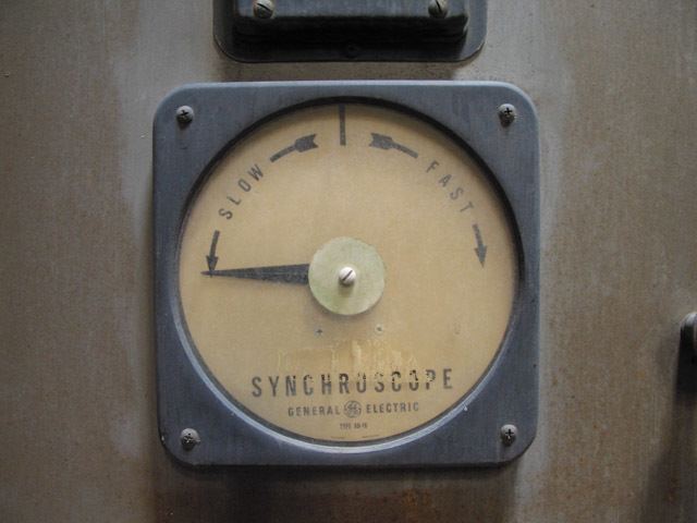
If the generator is turning at a lower frequency than the grid, the synchroscope needle rotates continually in the direction (usually counterclockwise) marked "slow" or "lag" on the dial to indicate that the generator is running slower than, or lagging behind, the grid. If the generator is running faster than the grid, the needle rotates continually in the opposite direction, marked "fast" or "lead". Next, the plant operator adjusts the speed of the generator until it is running at precisely the same speed (frequency) as the grid. As the frequency of the generator nears that of the grid, the synchroscope needle slows down and when the frequencies match, the needle stops rotating.
At this point, there is one more task to perform before the generator can be connected to the grid. Although the generator and the grid are now operating at the same frequency, they are not necessarily at the same position in the rotational cycle as each other. If two electrical networks operating at two different phase angles were to be connected to each other, a fault similar to a short circuit would occur and most likely destroy the generator and damage the grid.
The position (as opposed to rotation) of the needle on a synchroscope indicates the phase angle between the two systems. The angle between the systems is zero when the synchroscope needle is pointing directly to the line in between the "slow" and "fast" markings on the dial. (In the picture example in this article, the zero-phase-angle position is straight upwards, at the twelve o'clock position.)
If the needle reads "fast," then the plant's generator is slowed down by a very small amount and the needle turns counterclockwise (toward the zero mark). Alternatively, if the needle reads "slow," then the plant operator speeds the generator up slightly, and the needle turns clockwise. Slightly before the needle reaches the zero mark, the plant operator returns the generator to the grid frequency in order to stop the needle when it reaches the zero mark. When the needle is at zero and is not moving, the two systems are synchronized.
Once the two systems are synchronized, they can be safely connected.
Depending on the application and the circuit design, the breaker is closed when the synchroscope is pointing at approximately 5 minutes to noon, while traveling slowly in the fast direction, to allow the incoming generator to come onto the grid as a source. The purpose of this action is to prevent the possibility of the oncoming generator paralleling onto the grid as a load. This has the potential to cause the generator to operate as a motor which can cause damage to the generator and the prime mover (such as a steam turbine or Diesel engine). The machine may be protected from this occurrence by a "reverse power" trip.
In some power plants, a set of lamps may be connected between the generator and system busses (or between the instrument transformers connected to those busses) as a backup to the synchroscope instrument. The lamps flicker at the difference between system and generator frequency. The lamps can be connected to go dark when the phase voltages are identical and in-phase.
Multiengine vehicles
In addition to synchronizing generators to power systems, similar frequency-difference indicating instruments are used on multiengine ships and aircraft to allow the operators to exactly synchronize the speed of engines. This helps reduce the noise and vibration due to slight differences, for example, in the speeds of two propellers on an aircraft. In this application a synchroscope responds to slight speed differences that would not be visible on an engine tachometer.