 | ||
Symbolic circuit analysis is a formal technique of circuit analysis to calculate the behaviour or characteristic of an electric/electronic circuit with the independent variables (time or frequency), the dependent variables (voltages and currents), and (some or all of) the circuit elements represented by symbols.
Contents
- Frequency domain expressions
- Types of symbolic network functions
- Network function with s as the only variable
- Semi symbolic network function
- Fully symbolic network function
- Sequence of Expressions form
- References
When analysing electric/electronic circuits, we may ask two types of questions: What is the value of certain circuit variable (voltage, current, resistance, gain, etc.) or what is the relationship between some circuit variables or between a circuit variable and circuit components and frequency (or time). Such relationship may take the form of a graph, where numerical values of a circuit variable are plotted versus frequency or component value (the most common example would be a plot of the magnitude of a transfer function vs. frequency).
Symbolic circuit analysis is concerned with obtaining those relationships in symbolic form, i.e., in the form of analytical expression, where the complex frequency (or time) and some or all of the circuit components are represented by symbols.
Frequency domain expressions
In the frequency domain the most common task of symbolic circuit analysis is to obtain the relationship between input and output variables in the form of a rational function in the complex frequency
The above relationship is often called the network function. For physical systems,
where
While there are several methods for generating coefficients
Types of symbolic network functions
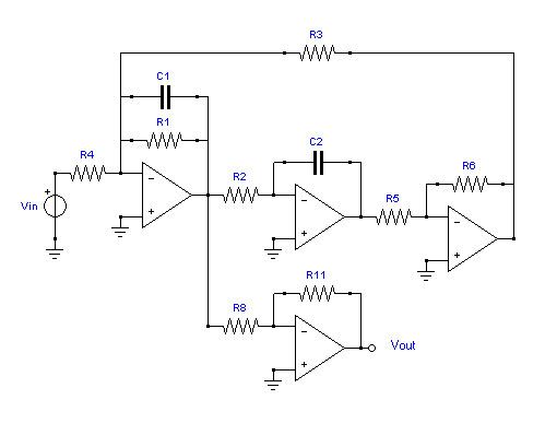
Depending on which parameters are kept as symbols, we may have several different types of symbolic network functions. This is best illustrated on an example. Consider, for instance, the biquad filter circuit with ideal op amps, shown below. We want to obtain a formula for its voltage transmittance (also called the voltage gain) in the frequency domain,
Network function with s as the only variable
If the complex frequency
Semi-symbolic network function
If the complex frequency
Fully symbolic network function
If the complex frequency
All expressions above are extremely useful in obtaining insight into operation of the circuit and understanding how each component contributes to the overall circuit performance. As the circuit size increases, however, the number of terms in such expressions grows exponentially. So, even for relatively simple circuits, the formulae become too long to be of any practical value. One way to deal with this problem is to omit numerically insignificant terms from the symbolic expression, keeping the inevitable error below the predetermined limit.
Sequence of Expressions form
Another possibility to shorten the symbolic expression to manageable length is to represent the network function by a sequence of expressions (SoE). Of course, the interpretability of the formula is lost, but this approach is very useful for repetitive numerical calculations. A software package STAINS (Symbolic Two-port Analysis via Internal Node Suppression) has been developed to generate such sequences. There are several types of SoE that can be obtained from STAINS. For example, the compact SoE for
The above sequence contains fractions. If this is not desirable (when divisions by zero appear, for instance), we may generate a fractionless SoE:
x1 = -G2*G5x2 = G6*s*C2x3 = -G4*x2x4 = x1*G3-(G1+s*C1)*x2x5 = x3*G8x6 = -G11*x4Ts = -x5/x6Yet another way to shorten the expression is to factorise polynomials
For larger circuits, however, factorisation becomes a difficult combinatorial problem and the final result may be impractical for both interpretation and numerical calculations.
