The stress intensity factor,
K
, is used in fracture mechanics to predict the stress state ("stress intensity") near the tip of a crack caused by a remote load or residual stresses. It is a theoretical construct usually applied to a homogeneous, linear elastic material and is useful for providing a failure criterion for brittle materials, and is a critical technique in the discipline of damage tolerance. The concept can also be applied to materials that exhibit small-scale yielding at a crack tip.
The magnitude of
K
depends on sample geometry, the size and location of the crack, and the magnitude and the modal distribution of loads on the material.
Linear elastic theory predicts that the stress distribution (
σ
i
j
) near the crack tip, in polar coordinates (
r
,
θ
) with origin at the crack tip, has the form
σ
i
j
(
r
,
θ
)
=
K
2
π
r
f
i
j
(
θ
)
+
h
i
g
h
e
r
o
r
d
e
r
t
e
r
m
s
where
K
is the stress intensity factor (with units of stress
×
length1/2) and
f
i
j
is a dimensionless quantity that varies with the load and geometry. This relation breaks down very close to the tip (small
r
) because as
r
goes to 0, the stress
σ
i
j
goes to
∞
. Plastic distortion typically occurs at high stresses and the linear elastic solution is no longer applicable close to the crack tip. However, if the crack-tip plastic zone is small, it can be assumed that the stress distribution near the crack is still given by the above relation.
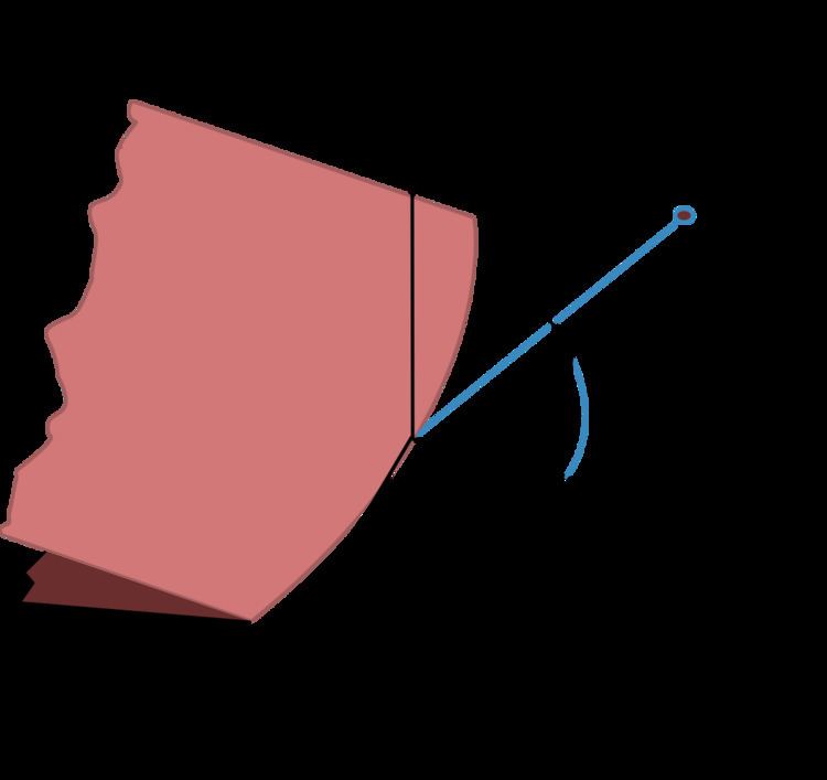
Three linearly independent cracking modes are used in fracture mechanics. These load types are categorized as Mode I, II, or III as shown in the figure. Mode I, shown to the left, is an opening (tensile) mode where the crack surfaces move directly apart. Mode II is a sliding (in-plane shear) mode where the crack surfaces slide over one another in a direction perpendicular to the leading edge of the crack. Mode III is a tearing (antiplane shear) mode where the crack surfaces move relative to one another and parallel to the leading edge of the crack. Mode I is the most common load type encountered in engineering design.
Different subscripts are used to designate the stress intensity factor for the three different modes. The stress intensity factor for mode I is designated
K
I
and applied to the crack opening mode. The mode II stress intensity factor,
K
I
I
, applies to the crack sliding mode and the mode III stress intensity factor,
K
I
I
I
, applies to the tearing mode. These factors are formally defined as:
K
I
=
lim
r
→
0
2
π
r
σ
y
y
(
r
,
0
)
K
I
I
=
lim
r
→
0
2
π
r
σ
y
x
(
r
,
0
)
K
I
I
I
=
lim
r
→
0
2
π
r
σ
y
z
(
r
,
0
)
.
Relationship to energy release rate and J-integral
The strain energy release rate (
G
) for a crack under mode I loading is related to the stress intensity factor by
G
=
K
I
2
(
1
−
ν
2
E
)
where
E
is the Young's modulus and
ν
is the Poisson's ratio of the material. The material is assumed to be an isotropic, homogeneous, and linear elastic. Plane strain has been assumed and the crack has been assumed to extend along the direction of the initial crack. For plane stress conditions, the equivalent relation is
G
=
K
I
2
(
1
E
)
.
For pure mode II loading, we have similar relations
G
=
K
I
I
2
(
1
−
ν
2
E
)
or
G
=
K
I
I
2
(
1
E
)
.
For pure mode III loading,
G
=
K
I
I
I
2
(
1
2
μ
)
where
μ
is the shear modulus. For general loading in plane strain, the relationship between the strain energy and the stress intensity factors for the three modes is
G
=
K
I
2
(
1
−
ν
2
E
)
+
K
I
I
2
(
1
−
ν
2
E
)
+
K
I
I
I
2
(
1
2
μ
)
.
A similar relation is obtained for plane stress by adding the contributions for the three modes.
The above relations can also be used to connect the J-integral to the stress intensity factor because
G
=
J
=
∫
Γ
(
W
d
x
2
−
t
⋅
∂
u
∂
x
1
d
s
)
.
The stress intensity factor,
K
, is a parameter that amplifies the magnitude of the applied stress that includes the geometrical parameter
Y
(load type). Stress intensity in any mode situation is directly proportional to the applied load on the material. If a very sharp crack can be made in a material, the minimum value of
K
I
can be empirically determined, which is the critical value of stress intensity required to propagate the crack. This critical value determined for mode I loading in plane strain is referred to as the critical fracture toughness (
K
I
c
) of the material.
K
I
c
has units of stress times the root of a distance. The units of
K
I
c
imply that the fracture stress of the material must be reached over some critical distance in order for
K
I
c
to be reached and crack propagation to occur. The Mode I critical stress intensity factor,
K
I
c
, is the most often used engineering design parameter in fracture mechanics and hence must be understood if we are to design fracture tolerant materials used in bridges, buildings, aircraft, or even bells. Polishing cannot detect a crack. Typically, if a crack can be seen it is very close to the critical stress state predicted by the stress intensity factor.
The G-criterion is a fracture criterion that relates the critical stress intensity factor (or fracture toughness) to the stress intensity factors for the three modes. This failure criterion is written as
K
c
2
=
K
I
2
+
K
I
I
2
+
E
′
2
μ
K
I
I
I
2
where
K
c
is the fracture toughness,
E
′
=
E
/
(
1
−
ν
2
)
for plane strain and
E
′
=
E
for plane stress. The critical stress intensity factor for plane stress is often written as
K
c
.