
 | ||
A squirrel-cage rotor is the rotating part (rotor) used in the most common form of AC induction motor. It consists of a cylinder of steel with aluminum or copper conductors embedded in its surface. An electric motor with a squirrel-cage rotor is termed a squirrel-cage motor. It consist of a stationary and a rotating parts. The rotating rotor is known as the squirrel cage rotor as it resembles a squirrel cage, whereas the stator is completely wound by copper wires with a proper insulation.
Contents
Structure
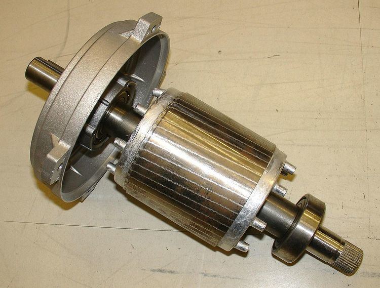
The motor rotor shape is a cylinder mounted on a shaft. Internally it contains longitudinal conductive bars (usually made of aluminium or copper) set into grooves and connected at both ends by shorting rings forming a cage-like shape. The name is derived from the similarity between this rings-and-bars winding and a squirrel cage.
The solid core of the rotor is built with stacks of electrical steel laminations. Figure 3 shows one of many laminations used. The rotor has a smaller number of slots than the stator and must be a non-integer multiple of stator slots so as to prevent magnetic interlocking of rotor and stator teeth at the starting instant.
The rotor bars may be made either of copper or aluminium. A very common structure uses die cast aluminium poured into the rotor after the laminations are stacked. Some larger motors have aluminium or copper bars which are welded or brazed to end-rings. Since the voltage developed in the squirrel cage winding is very low, no intentional insulation layer is present between the bars and the rotor steel.
Theory
The field windings in the stator of an induction motor set up a rotating magnetic field through the rotor. The relative motion between this field and the rotor induces electric current in the conductive bars. In turn these currents lengthwise in the conductors react with the magnetic field of the motor to produce force acting at a tangent orthogonal to the rotor, resulting in torque to turn the shaft. In effect the rotor is carried around with the magnetic field but at a slightly slower rate of rotation. The difference in speed is called slip and increases with load.
The conductors are often skewed slightly along the length of the rotor to reduce noise and smooth out torque fluctuations that might result at some speeds due to interactions with the pole pieces of the stator. The number of bars on the squirrel cage determines to what extent the induced currents are fed back to the stator coils and hence the current through them. The constructions that offer the least feedback employ prime numbers of bars.
The iron core serves to carry the magnetic field through the rotor conductors. Because the magnetic field in the rotor is alternating with time, the core uses construction similar to a transformer core to reduce core energy losses. It is made of thin laminations, separated by varnish insulation, to reduce eddy currents circulating in the core. The material is a low carbon but high silicon iron with several times the resistivity of pure iron, further reducing eddy-current loss, and low coercivity to reduce hysteresis loss.
The same basic design is used for both single-phase and three-phase motors over a wide range of sizes. Rotors for three-phase will have variations in the depth and shape of bars to suit the design classification. Generally, thick bars have good torque and are efficient at low slip, since they present lower resistance to the EMF. As the slip increases, skin effect starts to reduce the effective depth and increases the resistance, resulting in reduced efficiency but still maintaining torque.
The shape and depth of the rotor bars can be used to vary the speed-torque characteristics of the induction motor. At standstill, the revolving magnetic field passes the rotor bars at a high rate, inducing line-frequency current into the rotor bars. Due to the skin effect, the induced current tends to flow at the outer edge of the winding. As the motor accelerates, the slip frequency decreases and induced current flows at greater depths in the winding. By tapering the profile of the rotor bars to vary their resistance at different depths, or by constructing a double squirrel cage, the motor can be arranged to produce more or less torque at standstill and near its synchronous speed.
Practical demonstration
To demonstrate how the cage rotor works, the stator of a single-phase motor and a copper pipe (as rotor) may be used. If adequate AC power is applied to the stator, an alternating magnetic field will revolve around within the stator. If the copper pipe is inserted inside the stator, there will be an induced current in the pipe, and this current will produce a magnetic field in the pipe. The interaction between the stator's revolving magnetic field and the copper-pipe-rotor's induced magnetic field produces a torque and thus rotation.
Use in synchronous motors
A synchronous motor may have a squirrel-cage winding embedded in its rotor, used to increase the motor starting torque and so decrease the time to accelerate to synchronous speed. The squirrel cage winding of a synchronous machine will generally be smaller than for an induction machine of similar rating. When the rotor is turning at the same speed as the stator's revolving magnetic field, no current is induced into the squirrel-cage windings and the windings will have no further effect on the operation of the synchronous motor at steady-state.
The squirrel cage winding in some machines provides a damping effect for load or system disturbances, and in this role may be designated as an "amortisseur" windings. Large machines may only have amortisseur bars in the individual pole faces, not interconnected between poles. Because the squirrel cage winding is not large enough to dissipate the heat of continuous operation, large synchronous machines often have protective relays to detect when the machine has fallen out of synchronization with the supply voltage.
Induction generators
Three phase squirrel cage induction motors can also be used as generators. For this to work the motor must either be connected to a grid supply or an arrangement of capacitors to provide excitation current. For the motor to work as a generator instead of a motor the rotor must be spun faster than its stator's synchronous speed. This will cause the motor to generate power after building up its residual magnetism.