
 | ||
A speckle pattern is an intensity pattern produced by the mutual interference of a set of wavefronts. This phenomenon has been investigated by scientists since the time of Newton, but speckles have come into prominence since the invention of the laser and have now found a variety of applications.
Contents
- Explanation
- Subjective speckles
- Objective speckles
- Near field speckles
- Optical vortices in speckle patterns
- Applications
- Reduction
- References
Speckle patterns typically occur in diffuse reflections of monochromatic light such as laser light. Such reflections may occur on materials such as paper, white paint, rough surfaces, or in media with a large number of scattering particles in space, such as airborne dust or in cloudy liquids.
Explanation
The speckle effect is a result of the interference of many waves of the same frequency, having different phases and amplitudes, which add together to give a resultant wave whose amplitude, and therefore intensity, varies randomly. If each wave is modelled by a vector, then it can be seen that if a number of vectors with random angles are added together, the length of the resulting vector can be anything from zero to the sum of the individual vector lengths—a 2-dimensional random walk, sometimes known as a drunkard's walk. In the limit of many interfering waves the distribution of intensities (which go as the square of the vector's length) becomes exponential
When a surface is illuminated by a light wave, according to diffraction theory, each point on an illuminated surface acts as a source of secondary spherical waves. The light at any point in the scattered light field is made up of waves which have been scattered from each point on the illuminated surface. If the surface is rough enough to create path-length differences exceeding one wavelength, giving rise to phase changes greater than 2π, the amplitude, and hence the intensity, of the resultant light varies randomly.
If light of low coherence (i.e., made up of many wavelengths) is used, a speckle pattern will not normally be observed, because the speckle patterns produced by individual wavelengths have different dimensions and will normally average one another out. However, speckle patterns can be observed in polychromatic light in some conditions.
Subjective speckles
When a rough surface which is illuminated by a coherent light (e.g. a laser beam) is imaged, a speckle pattern is observed in the image plane; this is called a “subjective speckle pattern” – see image above. It is called "subjective" because the detailed structure of the speckle pattern depends on the viewing system parameters; for instance, if the size of the lens aperture changes, the size of the speckles change. If the position of the imaging system is altered, the pattern will gradually change and will eventually be unrelated to the original speckle pattern.
This can be explained as follows. Each point in the image can be considered to be illuminated by a finite area in the object. The size of this area is determined by the diffraction-limited resolution of the lens which is given by the Airy disk whose diameter is 2.4λu/D, where λ is the wavelength of the light, u is the distance between the object and the lens, and D is the diameter of the lens aperture. (This is a simplified model of diffraction-limited imaging).
The light at neighbouring points in the image has been scattered from areas which have many points in common and the intensity of two such points will not differ much. However, two points in the image which are illuminated by areas in the object which are separated by the diameter of the Airy disk, have light intensities which are unrelated. This corresponds to a distance in the image of 2.4λv/D where v is the distance between the lens and the image. Thus, the ‘size’ of the speckles in the image is of this order.
The change in speckle size with lens aperture can be observed by looking at a laser spot on a wall directly, and then through a very small hole. The speckles will be seen to increase significantly in size.
Objective speckles
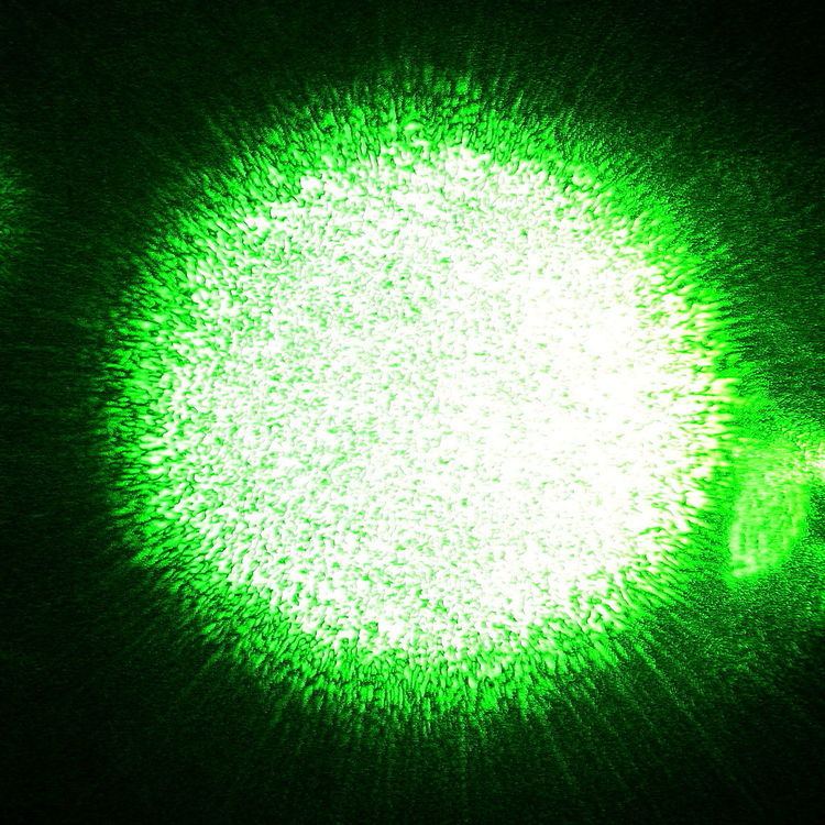
When laser light which has been scattered off a rough surface falls on another surface, it forms an “objective speckle pattern”. If a photographic plate or another 2-D optical sensor is located within the scattered light field without a lens, a speckle pattern is obtained whose characteristics depend on the geometry of the system and the wavelength of the laser. The speckle pattern in the figure was obtained by pointing a laser beam at the surface of a mobile phone so that the scattered light fell onto an adjacent wall. A photograph was then taken of the speckle pattern formed on the wall (strictly speaking, this also has a second subjective speckle pattern but its dimensions are much smaller than the objective pattern so it is not seen in the image)
The light at a given point in the speckle pattern is made up of contributions from the whole of the scattering surface. The relative phases of these waves vary across the surface, so that the sum of the individual waves varies randomly. The pattern is the same regardless of how it is imaged, just as if it were a painted pattern.
The "size" of the speckles is a function of the wavelength of the light, the size of the laser beam which illuminates the first surface, and the distance between this surface and the surface where the speckle pattern is formed. This is the case because when the angle of scattering changes such that the relative path difference between light scattered from the centre of the illuminated area compared with light scattered from the edge of the illuminated changes by λ, the intensity becomes uncorrelated. Dainty derives an expression for the mean speckle size as λz/L where L is the width of the illuminated area and z is the distance between the object and the location of the speckle pattern.
Near-field speckles
Objective speckles are usually obtained in the far field (also called Fraunhofer region, that is the zone where Fraunhofer diffraction happens). This means that they are generated "far" from the object that emits or scatters light. Speckles can be observed also close to the scattering object, in the near field (also called Fresnel region, that is, the region where Fresnel diffraction happens). This kind of speckles are called near field speckles. See near and far field for a more rigorous definition of "near" and "far".
The statistical properties of a far-field speckle pattern (i.e., the speckle form and dimension) depend on the form and dimension of the region hit by laser light. By contrast, a very interesting feature of near field speckles is that their statistical properties are closely related to the form and structure of the scattering object: objects that scatter at high angles generate small near field speckles, and vice versa. Under Rayleigh-Gans condition, in particular, speckle dimension mirrors the average dimension of the scattering objects, while, in general, the statistical properties of near field speckles generated by a sample depend on the light scattering distribution.
Actually, the condition under which the near field speckles appear has been described as more strict than the usual Fresnel condition.
Optical vortices in speckle patterns
Speckle interference pattern may be decomposed in the sum of plane waves. There exist a set of points where amplitude of electromagnetic field is exactly zero. These points had been recognized as dislocations of wave trains . These phase dislocations of electromagnetic field are known as optical vortices.
There is a circular energy flow around each vortex core. Thus each vortex in the speckle pattern carries optical angular momentum. The angular momentum density is given by:
Typically vortices appear in speckle pattern in pairs. These vortex - antivortex pairs are placed randomly in space. One may show that electromagnetic angular momentum of each vortex pair is close to zero. In phase conjugating mirrors based on stimulated Brillouin scattering optical vortices excite acoustical vortices.
Apart from formal decomposition in Fourier series the speckle pattern may be composed for plane waves emitted by tilted regions of the phase plate. This approach significantly simplifies numerical modelling.
Applications
When lasers were first invented, the speckle effect was considered to be a severe drawback in using lasers to illuminate objects, particularly in holographic imaging because of the grainy image produced. It was later realized that speckle patterns could carry information about the object's surface deformations, and this effect is exploited in holographic interferometry and electronic speckle pattern interferometry. The speckle effect is also used in speckle imaging and in eye testing using speckle.
Speckle is the chief limitation of coherent lidar and coherent imaging in optical heterodyne detection.
In the case of near field speckles, the statistical properties depend on the light scattering distribution of a given sample. This allows the use of near field speckle analysis to detect the scattering distribution; this is the so-called near-field scattering technique.
When the speckle pattern changes in time, due to changes in the illuminated surface, the phenomenon is known as dynamic speckle, and it can be used to measure activity, by means of, for example, an optical flow sensor (optical computer mouse). In biological materials, the phenomenon is known as biospeckle.
Reduction
Speckle is considered to be a problem in laser based display systems like the Laser TV. Speckle is usually quantified by the speckle contrast. Speckle contrast reduction is essentially the creation of many independent speckle patterns, so that they average out on the retina/detector. This can be achieved by,
Rotating diffusers—which destroys the spatial coherence of the laser light—can also be used to reduce the speckle. Moving/vibrating screens may also be solutions. The Mitsubishi Laser TV appears to use such a screen which requires special care according to their product manual. A more detailed discussion on laser speckle reduction can be found here.
Synthetic array heterodyne detection was developed to reduce speckle noise in coherent optical imaging and coherent differential absorption LIDAR.
In scientific applications, a spatial filter can be used to reduce speckle.